To control powerful loads in AC circuits are often used electromagnetic relays. The contact groups of these devices serve as an additional source of unreliability due to the tendency to burn, weld. Also, the possibility of sparking during switching looks like a disadvantage, which in some cases requires additional security measures. Therefore, electronic keys look preferable. One of the options for such a key is performed on triacs.
Content
What is a triac and why is it needed
In power electronics, one of the types is often used as a controlled switching element. thyristors - trinistors. Their advantages:
- absence of a contact group;
- lack of rotating and moving mechanical elements;
- small weight and dimensions;
- long resource, independent of the number of on-off cycles;
- low cost;
- high speed and quiet operation.
But when using trinistors in AC circuits, their one-way conduction becomes a problem. In order for the trinistor to pass current in two directions, one has to resort to tricks in the form of a parallel connection in the opposite direction of two trinistors controlled simultaneously. It seems logical to combine these two SCRs in one shell for ease of installation and size reduction. And this step was taken in 1963, when Soviet scientists and General Electric specialists almost simultaneously filed applications for registration of the invention of a symmetrical trinistor - triac (in foreign terminology, triac, triac - triode for alternative current).
In fact, the triac is not literally two trinistors placed in one case.
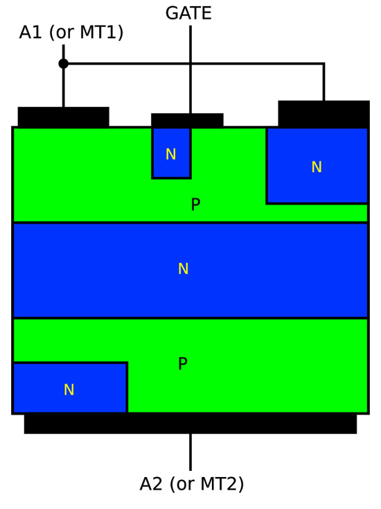
 The whole system is implemented on a single crystal with different p- and n-conductivity bands, and this structure is not symmetrical (although the current-voltage characteristic of a triac is symmetric with respect to the origin and is a mirrored I–V characteristic of a trinistor). And this is the fundamental difference between a triac and two trinistors, each of which must be controlled by a positive, in relation to the cathode, current.
The triac has no anode and cathode in relation to the direction of the transmitted current, but in relation to the control electrode, these conclusions are not equivalent. The terms “conditional cathode” (MT1, A1) and “conditional anode” (MT2, A2) are found in the literature. They are convenient to use to describe the operation of the triac.
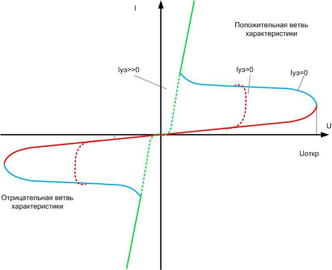
When a half-wave of any polarity is applied, the device is first locked (red section of the CVC).Also, as with the trinistor, the triggering of the triac can occur when the threshold voltage level is exceeded for any polarity of the sine wave (blue section). In electronic keys, this phenomenon (dynistor effect) is rather harmful. It must be avoided when choosing a mode of operation. The opening of the triac occurs by applying current to the control electrode. The greater the current, the earlier the key will open (red dashed area). This current is created by applying a voltage between the control electrode and the conditional cathode. This voltage must either be negative or have the same sign as the voltage applied between MT1 and MT2.
At a certain current value, the triac opens immediately and behaves like a normal diode - up to blocking (green dashed and solid areas). Improvement in technology leads to a decrease in the current consumed to completely unlock the triac. For modern modifications, it is up to 60 mA and below. But one should not get carried away with reducing the current in a real circuit - this can lead to an unstable opening of the triac.
Closing, like a conventional trinistor, occurs when the current drops to a certain limit (almost to zero). In the AC circuit, this occurs when the next passage through zero, after which it will be necessary to apply a control pulse again. In DC circuits, the controlled shutdown of the triac requires cumbersome technical solutions.
Features and limitations
There are restrictions on the use of a triac when switching a reactive (inductive or capacitive) load. In the presence of such a consumer in the AC circuit, the voltage and current phases are shifted relative to each other. The direction of the shift depends on the nature of the reactivity, and the magnitude - on the value of the reactive component. It has already been said that the triac turns off at the moment the current passes through zero. And the tension between MT1 and MT2 at this moment can be quite large. If the rate of change of voltage dU/dt at the same time exceeds the threshold value, then the triac may not close. To avoid this effect, parallel to the power path of the triac include varistors. Their resistance depends on the applied voltage, and they limit the rate of change of the potential difference. The same effect can be achieved by using an RC chain (snubber).
The danger from exceeding the rate of current rise when switching the load is associated with the finite time of the triggering of the triac. At the moment when the triac has not yet closed, it may turn out that a large voltage is applied to it and at the same time a sufficiently large through current flows through the power path. This can lead to the release of a large thermal power on the device, and the crystal may overheat. To eliminate this defect, it is necessary, if possible, to compensate for the reactivity of the consumer by sequential inclusion in the circuit of reactivity of approximately the same value, but of the opposite sign.
It should also be borne in mind that in the open state, about 1-2 V drops on the triac. But since the scope is powerful high-voltage switches, this property does not affect the practical use of triacs. The loss of 1-2 volts in a 220-volt circuit is comparable to the voltage measurement error.
Examples of using
The main area of \u200b\u200buse of the triac is the key in AC circuits.There are no fundamental restrictions on the use of a triac as a DC key, but there is no point in this either. In this case, it is easier to use a cheaper and more common trinistor.
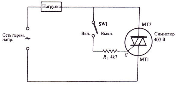
Like any key, the triac is connected to the circuit in series with the load. Turning the triac on and off controls the voltage supply to the consumer.
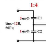
Also, the triac can be used as a voltage regulator on loads that do not care about the shape of the voltage (for example, incandescent lamps or thermal heaters). In this case, the control scheme looks like this.
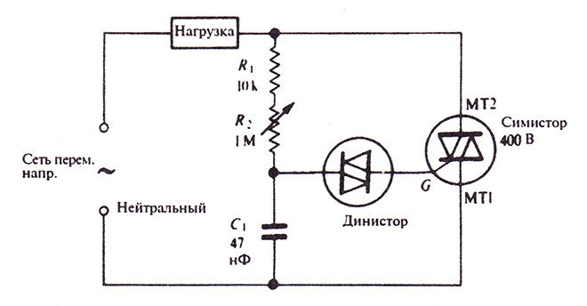
Here, a phase-shifting circuit is organized on resistors R1, R2 and capacitor C1. By adjusting the resistance, a shift in the beginning of the pulse is achieved relative to the transition of the mains voltage through zero. A dinistor with an opening voltage of about 30 volts is responsible for the formation of the pulse. When this level is reached, it opens and passes current to the control electrode of the triac. Obviously, this current coincides in direction with the current through the power path of the triac. Some manufacturers produce semiconductor devices called Quadrac. They have a triac and a dinistor in the control electrode circuit in one housing.
Such a circuit is simple, but its consumption current has a sharply non-sinusoidal shape, while interference is created in the supply network. To suppress them, it is necessary to use filters - at least the simplest RC chains.
Advantages and disadvantages
The advantages of the triac coincide with the advantages of the trinistor described above. To them, you just need to add the ability to work in AC circuits and simple control in this mode. But there are also disadvantages.They mainly concern the application area, which is limited by the reactive component of the load. It is not always possible to apply the protection measures suggested above. Also, the disadvantages include:
- increased sensitivity to noise and interference in the control electrode circuit, which can cause false alarms;
- the need to remove heat from the crystal - the arrangement of radiators compensates for the small dimensions of the device, and for switching powerful loads, the use contactors and relay becomes preferred;
- limitation on the operating frequency - it does not matter when operating at industrial frequencies of 50 or 100 Hz, but limits the use in voltage converters.
For the competent use of triacs, it is necessary to know not only the principles of operation of the device, but also its shortcomings, which determine the boundaries of the use of triacs. Only in this case the developed device will work for a long time and reliably.
Similar articles: