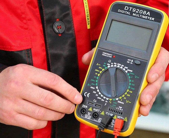
Capacitors are widely used in engineering. Their damage causes loss of performance of household appliances, electronics, and other devices. An external examination does not always give a correct conclusion about a malfunction, therefore, the capacitor is checked for damage by electrical measuring instruments - a multimeter or a tester.
Content
How to check the capacitance of a capacitor with a multimeter
If you know how to check the performance of a capacitor with a multimeter, you can avoid many troubles. To do this, test the main characteristics and parameters that affect the operation. On the body of the radio component are indicated:
- Rated capacity. Its value affects the amount of accumulated energy on the plates, which is formed when charging from a constant voltage source and is consumed in the electrical circuit during discharge.
- Rated voltage. An incorrectly selected value will lead to a breakdown of the dielectric.
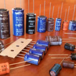
To determine the malfunctions, it is necessary to understand the types of capacitors, they are polar and non-polar.
Polar are called electrolytic, having a negative and positive conclusion. The polarity is indicated on the case (a minus is indicated by a tick) or determined by size - the output with a plus is longer. It is important to correctly connect an electrical measuring device for checking electrolytic capacitors: connect the “+” probe to the positive terminal, and the “-” probe to the negative terminal. Such a connection is also made when installing electrical circuits.
The remaining species are non-polar, so the method of connecting to the tester is not important.
We measure resistance
You can check the health of the capacitor by determining the resistance using the ohmmeter mode. At the same time, they check:
- internal break;
- breakdown
- short circuit.
If the part is included in the circuit, it is soldered. Next, perform the following actions:
- Examine the appearance. Bulging, smudges, darkening, weak fastening of the conclusions mean a malfunction.
- The capacitor is discharged with a metal object, a screwdriver, tweezers are used. Holding the handle of the tool, they touch two leads at once. Discharging may cause a spark.
- Set up the device to check the condition of the capacitor, use the ohmmeter function. The pointer selects the measurement limit in the Ω sector or continuity.
- Connect the probes of the electrical measuring device to the radio component. If it is necessary to check the electrolytic capacitor, then take into account the polarity.
- At the initial moment of time, the power supply of the multimeter charges the radio component, the charge rate is directly proportional to the capacitance.
- According to the display of the digital multimeter, a conclusion is made about the performance:
- if with an increase in the charge the indication smoothly increases from 0 to the number 1 (corresponding to infinity) - there is no malfunction;
- if the number 1 immediately appears - damage (break);
- if the number 0 immediately appears - a malfunction (short circuit or breakdown).
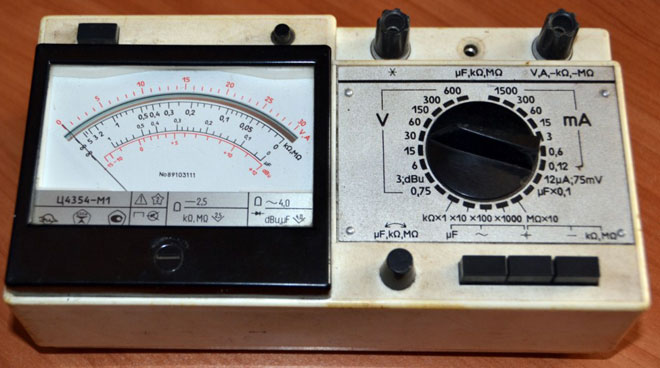
Using an analog device, the procedure for determining faults is repeated. According to the deviation of the arrow, the suitability for work is judged:
- smooth movement from 0 to the maximum value - no malfunction;
- the arrow remains on the number 0 - a short circuit, replacement is required;
- the arrow immediately shows the maximum value - a break.
To test a non-polar capacitor:
- first unload;
- on the measuring device, select the ohmmeter mode;
- set the measurement limit to megaohms;
- connect a tester to the capacitor;
- take a reading: if the resistance value is less than 2 megaohm - there is a malfunction, more than 2 megaohm or 1 - there is no malfunction.
Breakdown is defined as follows:
- apply a voltage that exceeds the nominal;
- resistance is measured: during breakdown, it does not change.
We measure the capacity
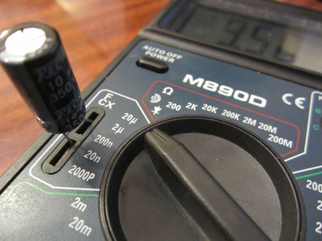
To check the capacitance of a capacitor, the multimeter must have this function. To make a measurement, use sockets Cx with polarity "plus" and "minus". When testing, the resulting value is compared with the nominal value. Procedure:
- Take charge.
- The switch sets the capacitance measurement limit in accordance with the nominal value.
- Cx sockets are used for measurement. If the element is electrolytic, pay attention to the polarity: the “positive” terminal is connected to the “+” socket, the “negative” terminal is connected to the “-” socket. They take evidence.
- Compare the measured value with the nominal value. If there is no large deviation, there is no malfunction. Otherwise, replacement is required.
To check the validity of a ceramic capacitor:
- He is being torn down.
- Set the capacitance measurement limit closest to the nominal value.
- Insert the leads into the sockets Cx, regardless of the polarity.
- Measure capacity. Compare the obtained value with the nominal value. If the reading corresponds to the specified value, the capacitor is not damaged. If it is very different or equal to 0, a replacement is required.
The deviation of the measured parameter by no more than 30% of the nominal value is allowed.
If there are no Cx sockets, the presence of capacitance is judged by an indirect method when measuring resistance with an analog device. For this:
- Take charge.
- Set the multimeter to ohmmeter mode.
- Connect the probes to the terminals of the capacitor, charge from the ohmmeter battery. By the time the arrow deflects to infinity, a conclusion is made about the capacity. When measuring up to 100 uF, the arrow deviates quickly, this indicates a small capacitance.
During operation, electrical parameters decrease, so they are periodically checked.
We measure voltage
Consider how the performance is determined by measuring the voltage. For this you should:
- Charge the radio component from a DC voltage source that is less than the nominal voltage.
- Set the measurement function to voltmeter mode. Select a limit equal to the power supply voltage.
- Connect the multimeter leads to the capacitor leads, respecting the polarity if required. Make a freeze.
- Compare the measured value with the power supply voltage. In the absence of large discrepancies, there is no malfunction. The true value will be at the initial time. Then decrease due to discharge.
Check without instruments
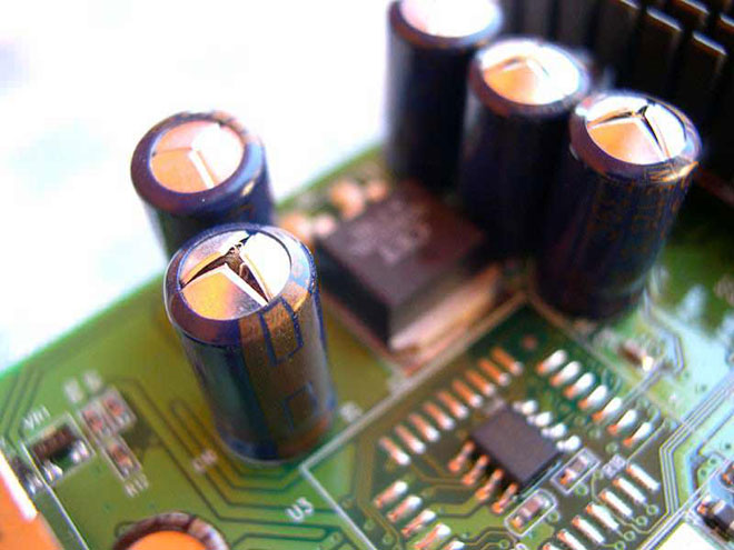
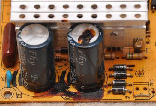
Without measurement of parameters, defects in appearance indicate a malfunction:
- spots on the surface of the case;
- swelling, deformation of the upper notch on imported electrolytic capacitors;
- electrolyte leakage.
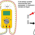
Other methods of fault control are used at home. Should:
- connect to a power source, the voltage should not exceed the nominal;
- take an LED (a low-voltage lamp with two wires), touch the leads of the LED to the legs of the capacitor;
- a flash of the LED (short-term glow of the lamp) will confirm the serviceability.
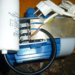
To determine the performance of a large capacitor:
- connect to a power source whose voltage is less than the nominal;
- remove the charge with a metal object.
The presence of a spark during discharge will confirm the suitability. When removing the charge, be careful, take protective measures, since the discharge is accompanied by a powerful spark and sound. To reduce the spark, a discharge through a resistor is used.
Features of checking capacitors of different types
There are many types of radio components that differ in the material of the dielectric, plates, type of electrolyte, so they have different methods for diagnosing the working condition.
To check the suitability of a ceramic capacitor, set the maximum measurement limit of an ohmmeter. A sign of serviceability will be a measured resistance of at least 2 MΩ. For other values, the part is changed.
To test a tantalum capacitor, choose the largest measurement limit in ohms. When the resistance is 0, it is changed. Before testing an electrolytic capacitor of large capacity and high voltage, maximum discharge is necessary. Residual voltage will damage the device.

SMD capacitors are non-polar, so they are tested as ceramic, determining suitability in ohmmeter mode.
A film capacitor with a short circuit will read 0. With an internal break, the analog multimeter will show infinity, the digital one will show 1.
Testing without desoldering
It is impossible to investigate the radio component without soldering, the reading will be incorrect from the influence of other elements of the circuit. The proximity of transformers, inductance, fuses introduces an error into the measurement. Connecting them in parallel or in series will increase or decrease the test result. For a correct assessment of the state, the capacitor is soldered.
Without soldering, you can approximately determine the operation of the circuit section. To do this, touch the probes to the legs of the part and measure the resistance. If the reading increases and then decreases, the part is good.
It must be remembered that capacitor monitoring is only possible up to a maximum value of 200 µF. Electrical measuring instruments do not measure large parameters. At a value of less than 0.25 μF, the capacitors are checked only for a short circuit.
Similar articles: