A transformer is an electromagnetic device used to convert alternating current of one voltage and frequency into alternating current of a different (or equal) voltage and the same frequency.
Content
The device and operation of the transformer
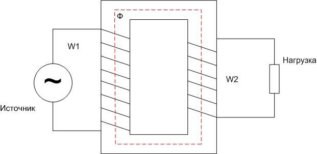
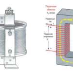
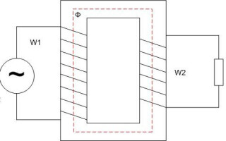
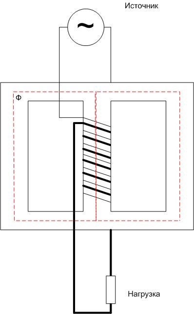
In the simplest case transformer contains one primary winding with the number of turns W1 and one secondary with the number of turns W2. Energy is supplied to the primary winding, the load is connected to the secondary. Energy is transferred by electromagnetic induction. To enhance electromagnetic coupling, in most cases, the windings are placed on a closed core (magnetic circuit).
If an alternating voltage U is applied to the primary winding1, then an alternating current I1, which creates a magnetic flux Ф of the same form in the core.This magnetic flux induces an EMF in the secondary winding. If a load is connected to the secondary circuit, a secondary current I2.
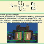
The voltage in the secondary winding is determined by the ratio of turns W1 and W2:
U2=U1*(W1/W2)=U1/k, where k is transformation ratio.
If k<1, then U2>U1, and such a transformer is called step-up. If k>1, then U2<U1, such the transformer is called step down. Since the output power of the transformer is equal to the input power (minus the losses in the transformer itself), we can say that Pout \u003d Pin, U1*I1=U2*I2 and I2=I1*k=I1*(W1/W2). Thus, in a lossless transformer, the input and output voltages are directly proportional to the ratio of winding turns. And the currents are inversely proportional to this ratio.
A transformer may have more than one secondary winding with different ratios. So, a transformer for powering household lamp equipment from a 220 volt network can have one secondary winding, for example, 500 volts to power anode circuits and 6 volts to power incandescent circuits. In the first case k<1, in the second - k>1.
The transformer works only with alternating voltage - for the occurrence of EMF in the secondary winding, the magnetic flux must change.
Types of cores for transformers
In practice, cores not only of the indicated shape are used. Depending on the purpose of the device, magnetic circuits can be performed in different ways.
Rod cores
The magnetic circuits of low-frequency transformers are made of steel with pronounced magnetic properties.To reduce eddy currents, the core array is assembled from separate plates electrically isolated from each other. To work at high frequencies, other materials are used, for example, ferrites.
The core considered above is called a core and consists of two rods. For single-phase transformers, three-rod magnetic cores are also used. They have less magnetic leakage flux and higher efficiency. In this case, both the primary and secondary windings are located on the central rod of the core.
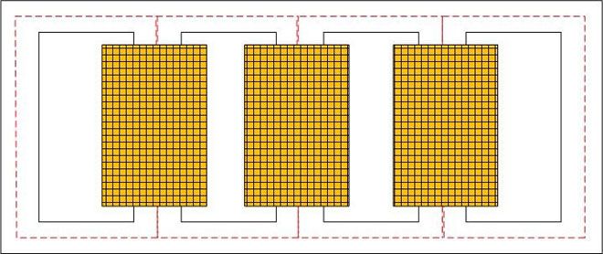
Three-phase transformers are also made on three-rod cores. They have the primary and secondary windings of each phase, each located on its own core. In some cases, five-rod magnetic circuits are used. Their windings are located in exactly the same way - each primary and secondary on its own rod, and the two extreme rods on each side are intended only for closing magnetic fluxes in certain modes.
armored
In the armored core, single-phase transformers are made - both coils are placed on the central core of the magnetic circuit. The magnetic flux in such a core closes similarly to a three-rod construct - through the side walls. The leakage flux is very small in this case.
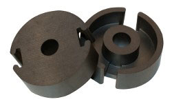
The advantages of this design include some gain in size and weight due to the possibility of denser filling of the core window with a winding, so it is advantageous to use armored cores for the manufacture of low-power transformers. This also results in a shorter magnetic circuit, which leads to a reduction in no-load losses.
The disadvantage is more difficult access to the windings for revision and repair, as well as the increased complexity of manufacturing insulation for high voltages.
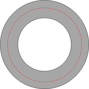
Toroidal
In toroidal cores, the magnetic flux is completely closed inside the core, and there is practically no leakage magnetic flux. But such transformers are difficult to wind, so they are used quite rarely, for example, in low-power adjustable autotransformers or in high-frequency devices where noise immunity is important.
Autotransformer
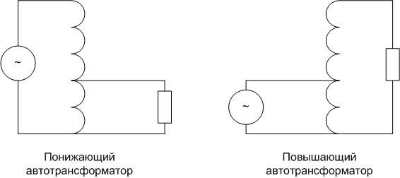
In some cases, it is advisable to use such transformers, which have not only a magnetic connection between the windings, but also an electrical one. That is, in step-up devices, the primary winding is part of the secondary, and in step-down devices, the secondary part of the primary. Such a device is called an autotransformer (AT).
A step-down autotransformer is not a simple voltage divider - magnetic coupling is also involved in the transfer of energy to the secondary circuit.
The advantages of autotransformers are:
- smaller losses;
- the possibility of smooth voltage regulation;
- smaller weight and size indicators (an autotransformer is cheaper, it is easier to transport it);
- lower cost due to the smaller required amount of material.
The disadvantages include the need to use insulation of both windings, designed for higher voltage, as well as the lack of galvanic isolation between the input and output, which can transfer the effects of atmospheric phenomena from the primary circuit to the secondary. In this case, the elements of the secondary circuit cannot be grounded.Also, the disadvantage of AT is considered to be increased short-circuit currents. For three-phase autotransformers, the windings are usually connected in a star with a grounded neutral, other connection schemes are possible, but too complicated and cumbersome. This is also a disadvantage that narrows the scope of autotransformers.
Application of transformers
The property of transformers to increase or decrease voltage is widely used in industry and in everyday life.
Voltage transformation
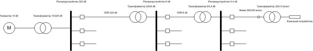
Different requirements are imposed on the level of industrial voltage at different stages. When generating electricity, it is unprofitable to use high-voltage generators for various reasons. Therefore, for example, generators for 6 ... 35 kV are used at hydroelectric power stations. To transport electricity, on the contrary, you need an increased voltage - from 110 kV to 1150 kV, depending on the distance. Further, this voltage is again reduced to the level of 6 ... 10 kV, distributed to local substations, from where it is reduced to 380 (220) volts and comes to the end consumer. In household and industrial appliances, it must also be lowered, usually to 3 ... 36 volts.
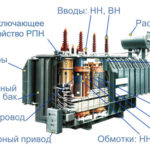
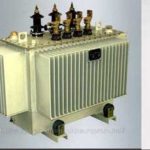
All these operations are carried out with using power transformers. They can be dry or oil-based. In the second case, the core with windings is placed in a tank with oil, which is an insulating and cooling medium.
Galvanic isolation
Galvanic isolation increases the safety of electrical appliances. If the device is powered not directly from a 220 volt network, where one of the conductors is connected to the ground, but through a 220/220 volt transformer, then the supply voltage will remain the same.But with simultaneous touching of the earth and secondary current-carrying parts of the circuit for the flow of current, there will be no current flow, and the danger of electric shock will be much lower.
Voltage measurement
In all electrical installations it is necessary to control the voltage level. If a voltage class up to 1000 volts is used, then the voltmeters are connected directly to live parts. In electrical installations above 1000 volts, this will not work - devices that can withstand such a voltage turn out to be too bulky and unsafe in the event of an insulation breakdown. Therefore, in such systems, voltmeters are connected to high voltage conductors through transformers with a convenient transformation ratio. For example, for 10 kV networks, instrument transformers 1:100 are used, the output is a standard voltage of 100 volts. If the voltage on the primary winding changes in amplitude, it simultaneously changes on the secondary. The voltmeter scale is usually graduated in the primary voltage range.
The transformer is a rather complex and expensive element for production and maintenance. However, in many areas these devices are indispensable, and there is no alternative to them.
Similar articles: