We all come across electrical appliances every day, it seems that our life stops without them. And each of them in the technical instructions indicates the power. Today we will figure out what it is, learn the types and methods of calculation.
Content
Power in an alternating current circuit
Electrical appliances connected to the mains operate in an alternating current circuit, so we will consider the power in these conditions. However, first, let's give a general definition of the concept.
Power - a physical quantity that reflects the rate of conversion or transmission of electrical energy.
In a narrower sense, they say that electrical power is the ratio of the work performed over a certain period of time to this period of time.
To paraphrase this definition less scientifically, it turns out that power is a certain amount of energy that is consumed by the consumer over a certain period of time. The simplest example is an ordinary incandescent lamp. The rate at which a light bulb converts the electricity it consumes into heat and light is its power. Accordingly, the higher this indicator is initially for a light bulb, the more it will consume energy, and the more light it will give.
Since in this case there is not only the process of converting electricity into some other (light, thermal, etc.), but also the process of oscillation of the electric and magnetic fields, a phase shift appears between the current and voltage, and this should be taken into account in further calculations.
When calculating the power in an alternating current circuit, it is customary to distinguish active, reactive and full components.
The concept of active power
Active "useful" power is that part of the power that directly characterizes the process of converting electrical energy into some other energy. Denoted by the Latin letter P and measured in watts (Tue).
Calculated according to the formula: P = U⋅I⋅cosφ,
where U and I are the rms value of the voltage and current of the circuit, respectively, cos φ is the cosine of the phase angle between voltage and current.
IMPORTANT! The formula described earlier is suitable for calculating circuits with voltage 220V, however, powerful units usually use a network with a voltage of 380V. In this case, the expression should be multiplied by the root of three or 1.73
The concept of reactive power
Reactive "harmful" power is the power that is generated during the operation of electrical appliances with an inductive or capacitive load, and reflects the ongoing electromagnetic oscillations. Simply put, this is the energy that passes from the power source to the consumer, and then returns back to the network.
Of course, it is impossible to use this component in business, moreover, it harms the power supply network in many ways, therefore they usually try to compensate for it.
This value is denoted by the Latin letter Q.
REMEMBER! Reactive power is not measured in conventional watts (Tue), and in reactive volt-amperes (Var).
Calculated according to the formula:
Q = U⋅I⋅sinφ,
where U and I are the rms value of the voltage and current of the circuit, respectively, sinφ is the sine of the phase shift angle between voltage and current.
IMPORTANT! When calculating, this value can be both positive and negative, depending on the phase movement.
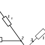
Capacitive and inductive loads
The main difference between reactive (capacitive and inductive) loads - the presence, in fact, of capacitance and inductance, which tend to store energy and later give it to the network.
An inductive load converts the energy of an electric current first into a magnetic field (during half a half cycle), and then converts the energy of the magnetic field into electric current and transmits it to the network. Examples are induction motors, rectifiers, transformers, electromagnets.
IMPORTANT! When operating an inductive load, the current curve always lags the voltage curve by half a half cycle.
A capacitive load converts the energy of an electric current into an electric field and then converts the energy of the resulting field back into an electric current.Both processes again proceed for half a half-cycle each. Examples are capacitors, batteries, synchronous motors.
IMPORTANT! During capacitive load operation, the current curve leads the voltage curve by half a half cycle.
Power factor cosφ
Power factor cosφ (read cosine phi) is a scalar physical quantity reflecting the efficiency of electrical energy consumption. Simply put, the coefficient cosφ shows the presence of a reactive part and the value of the received active part relative to the total power.
The coefficient cosφ is found through the ratio of active electrical power to apparent electrical power.
NOTE! In a more accurate calculation, the nonlinear distortions of the sinusoid should be taken into account, however, they are neglected in conventional calculations.
The value of this coefficient can vary from 0 to 1 (if the calculation is carried out as a percentage, then from 0% to 100%). From the calculation formula, it is not difficult to understand that the greater its value, the greater the active component, which means that the performance of the device is better.
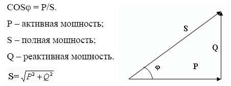
The concept of total power. Power Triangle
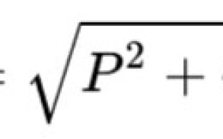
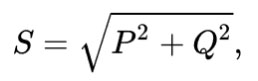
Apparent power is a geometrically calculated value equal to the root of the sum of the squares of active and reactive power, respectively. Designated with the Latin letter S.
You can also calculate the total power by multiplying the voltage and current, respectively.
S = U⋅I
IMPORTANT! Apparent power is measured in volt-amperes (VA).
The power triangle is a convenient representation of all the previously described calculations and relationships between active, reactive and apparent power.
The legs reflect the reactive and active components, the hypotenuse - the total power. According to the laws of geometry, the cosine of the angle φ is equal to the ratio of the active and total components, that is, it is the power factor.
How to find active, reactive and apparent power. Calculation example
All calculations are based on the previously mentioned formulas and the power triangle. Let's look at the problem most often encountered in practice.
Typically, electrical appliances are marked with active power and the value of the cosφ coefficient. With these data, it is easy to calculate the reactive and total components.
To do this, we divide the active power by the coefficient cosφ and get the product of current and voltage. This will be full power.
Further, based on the power triangle, we find the reactive power equal to the square of the difference between the squares of the apparent and active powers.
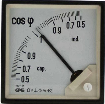
How cosφ is measured in practice
The value of the cosφ coefficient is usually indicated on the tags of electrical appliances, however, if it is necessary to measure it in practice, they use a specialized device - phase meter. Also, a digital wattmeter can easily cope with this task.
If the obtained coefficient cosφ is low enough, then it can be compensated practically. This is done mainly by including additional devices in the circuit.
- If it is necessary to correct the reactive component, then a reactive element should be included in the circuit, acting opposite to the already functioning device. To compensate for the operation of an induction motor, for example an inductive load, a capacitor is connected in parallel. An electromagnet is connected to compensate the synchronous motor.
- If it is necessary to correct non-linearity problems, a passive cosφ corrector is introduced into the circuit, for example, it can be a high inductance choke connected in series with the load.
Power is one of the most important indicators of electrical appliances, so knowing what it is and how it is calculated is useful not only for schoolchildren and people specializing in technology, but also for each of us.
Similar articles: