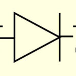
A semiconductor diode has many "professions". It can rectify voltage, untie electrical circuits, protect equipment from improper power supply. But there is a not quite usual kind of "work" of the diode, when its property of one-way conduction is used very indirectly. A semiconductor device for which the normal mode is reverse bias is called a zener diode.
Content
What is a zener diode, where is it used and what are
A zener diode, or a Zener diode (named after an American scientist who was the first to study and describe the properties of this semiconductor device), is a conventional diode with a p-n junction.Its feature is work in the section of the characteristic with a negative bias, that is, when the voltage is applied in reverse polarity. Such a diode is used as an independent stabilizer that maintains the consumer voltage constant, regardless of changes in the load current and fluctuations in the input voltage. Also, nodes on zener diodes are used as sources of reference voltage for other stabilizers with a developed circuit. Less commonly, a reverse diode is used as a pulse shaping element or surge protector.
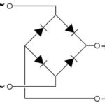
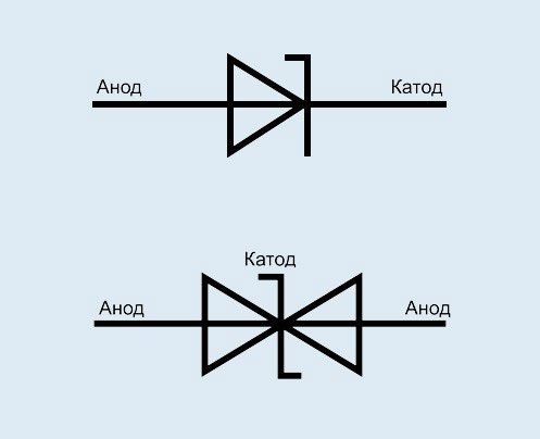
There are conventional zener diodes and two-anode ones. A two-anode zener diode is two diodes connected back to back in one housing. It can be replaced by two separate devices by switching them on according to the appropriate scheme.
Volt-ampere characteristic of the zener diode and its principle of operation
To understand the principle of operation of a zener diode, it is necessary to study its typical current-voltage characteristic (CVC).
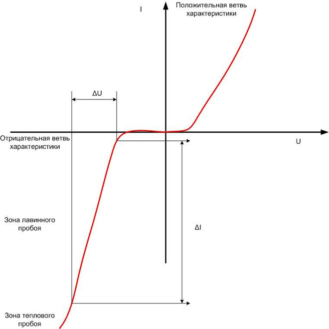
If a voltage is applied to the zener in the forward direction, as to a conventional diode, then it will behave like a conventional diode. At a voltage of about 0.6 V (for a silicon device), it will open and enter the linear section of the I–V characteristic. On the topic of the article, the behavior of the zener diode is more interesting when a voltage of reverse polarity is applied (negative branch of the characteristic). First, its resistance will increase sharply, and the device will stop passing current. But when a certain voltage value is reached, a sharp increase in current will occur, called breakdown. It has an avalanche character and disappears after the power is removed.If you continue to increase the reverse voltage, then the p-n junction will begin to heat up and enter the thermal breakdown mode. Thermal breakdown is irreversible and means the failure of the zener diode, so you should not put the diode into this mode.
An interesting area of operation of a semiconductor device in the avalanche breakdown mode. Its shape is close to linear, and it has a high steepness. This means that with a large change in current (ΔI), the change in voltage drop across the zener diode is relatively small (ΔU). And this is stabilization.
This behavior when applying a reverse voltage is typical for any diode. But the peculiarity of the zener diode is that its parameters in this section of the CVC are normalized. Its stabilization voltage and slope are given (with a certain spread) and are important parameters that determine the suitability of the device in the circuit. You can find them in reference books. Ordinary diodes can also be used as zener diodes - if you remove their CVC and among them there is a suitable characteristic. But this is a long, laborious process with a non-guaranteed result.
The main characteristics of the zener diode
To choose a Zener diode for existing purposes, you need to know several important parameters. These characteristics will determine the suitability of the selected device for solving the tasks.
Rated stabilization voltage
The first parameter of the zener that you need to pay attention to when choosing is the stabilization voltage, which is determined by the start point of the avalanche breakdown. It begins with the selection of a device for use in the circuit.For different instances of ordinary zener diodes, even of the same type, the voltage has a spread in the region of several percent, for precision ones the difference is lower. If the nominal voltage is not known, it can be determined by assembling a simple circuit. You should prepare:
- ballast resistor 1 ... 3 kOhm;
- adjustable voltage source;
- voltmeter (you can use a tester).
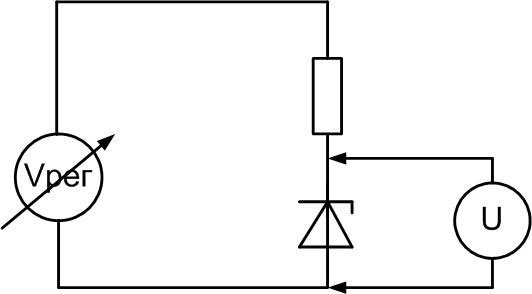
It is necessary to raise the voltage of the power source from zero, controlling the voltage growth at the zener diode using a voltmeter. At some point, it will stop, despite a further increase in the input voltage. This is the actual stabilization voltage. If there is no regulated source, you can use a power supply with a constant output voltage obviously higher than Ustabilization. The scheme and principle of measurement remain the same. But there is a risk of failure of the semiconductor device due to the excess of the operating current.
Zener diodes are used to work with voltages from 2 ... 3 V to 200 V. To form a stable voltage below this range, other devices are used - stabistors operating in the direct section of the CVC.
Operating current range
The current at which the zener diodes perform their function is limited from above and below. From below, it is limited by the beginning of the linear section of the reverse branch of the CVC. At lower currents, the characteristic does not provide a constant voltage mode.
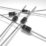
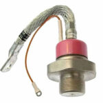
The upper value is limited by the maximum power dissipation that a semiconductor device is capable of and depends on its design. Zener diodes in a metal case are designed for more current, but do not forget about the use of heat sinks.Without them, the maximum allowable dissipation power will be significantly less.
Differential resistance
Another parameter that determines the operation of the zener diode is the differential resistance Rst. It is defined as the ratio of the change in voltage ΔU to the change in current ΔI that caused it. This value has the dimension of resistance and is measured in ohms. Graphically, this is the tangent of the slope of the working section of the characteristic. Obviously, the lower the resistance, the better the stabilization quality. For an ideal (not existing in practice) zener diode, Rst is equal to zero - any increase in current will not cause any change in voltage, and the I–V characteristic section will be parallel to the y-axis.
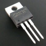
Zener diode marking
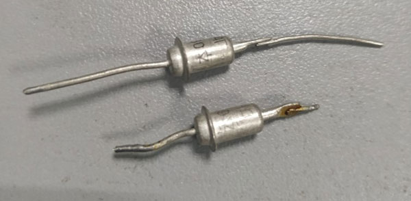
Domestic and imported zener diodes in a metal case are marked simply and clearly. They are marked with the name of the device and the location of the anode and cathode in the form of a schematic designation.
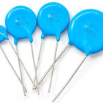
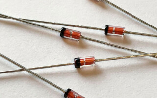
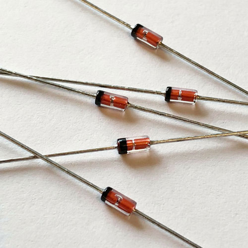
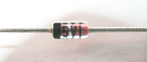
Devices in a plastic case are marked with rings and dots of various colors on the cathode and anode sides. By the color and combination of characters, you can determine the type of device, but for this you have to look into reference books or use calculator programs. Both can be found on the internet.
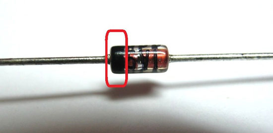
Sometimes a stabilization voltage is applied to low-power zener diodes.
Zener diode switching circuits
The main circuit for switching on a zener diode is in series with resistor, which sets the current through the semiconductor device and takes on the excess voltage. The two elements make common divisor. When the input voltage changes, the drop across the zener diode remains constant, while the drop across the resistor changes.
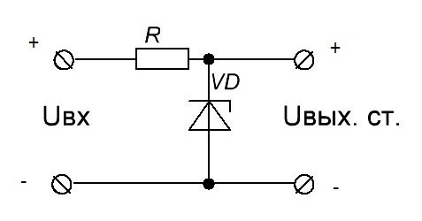
Such a circuit can be used independently and is called a parametric stabilizer. It maintains the voltage at the load constant, despite fluctuations in the input voltage or current drawn (within certain limits). A similar block is also used as an auxiliary circuit where a reference voltage source is needed.
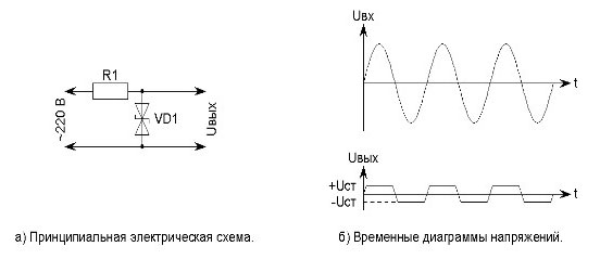
Such inclusion is also used as a protection of sensitive equipment (sensors, etc.) from abnormal occurrence of high voltage in the power or measurement line (constant or random impulses). Anything above the stabilization voltage of the semiconductor device is "cut off". Such a scheme is called a "Zener barrier".
Previously, the property of the zener diode to “cut off” the voltage peaks was widely used in pulse shaper circuits. Two-anode devices were used in alternating current circuits.
But with the development of transistor technology and the advent of integrated circuits, this principle was rarely used.
If there is no zener diode at hand for the desired voltage, it can be made up of two. The total stabilization voltage will be equal to the sum of the two voltages.
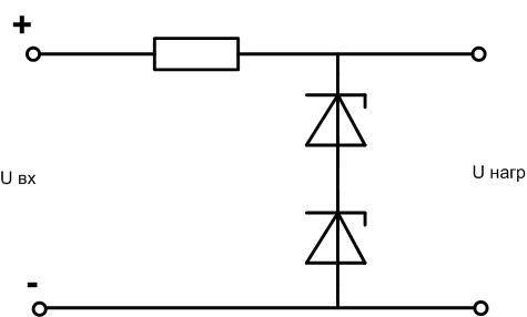
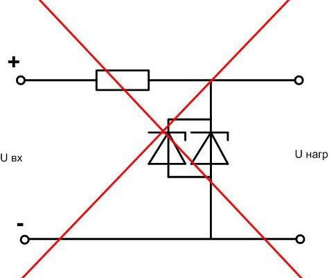
Important! Do not connect zener diodes in parallel to increase the operating current! The spread of current-voltage characteristics will lead to the output of one zener diode into the zone of thermal breakdown, then the second one will fail due to the excess of the load current.
Although in the technical documentation of the times of the USSR it is allowed parallel inclusion zeners in parallel, but with the proviso that the devices must be of the same type and the total actual dissipation power during operation should not exceed the allowable for a single zener diode. That is, an increase in the operating current under this condition cannot be achieved.
To increase the allowable load current, another scheme is used. The parametric stabilizer is supplemented with a transistor, and an emitter follower is obtained with a load in the emitter circuit and a stable transistor base voltage.
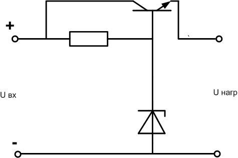
In this case, the output voltage of the stabilizer will be less than Ustabilization by the amount of voltage drop at the emitter junction - for a silicon transistor, about 0.6 V. To compensate for this decrease, you can turn on a diode in series with the zener diode in the forward direction.
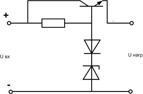
In this way (by turning on one or more diodes), you can adjust the output voltage of the stabilizer upwards within a small range. If you need to radically increase Uout, it is better to turn on one more zener diode in series.
The scope of the zener diode in electronic circuits is extensive. With a conscious approach to the choice, this semiconductor device will help solve many problems assigned to the developer.
Similar articles: