Resistors are among the most widely used elements in electronics. This name has long gone out of the narrow framework of the terminology of radio amateurs. And for anyone who is at least a little interested in electronics, the term should not cause misunderstanding.
Content
What is a resistor
The simplest definition is as follows: a resistor is an element of an electrical circuit that resists the current flowing through it. The name of the element comes from the Latin word "resisto" - "I resist", radio amateurs often call this part that way - resistance.
Consider what resistors are, what resistors are for. The answers to these questions imply familiarity with the physical meaning of the basic concepts of electrical engineering.
To explain the principle of operation of the resistor, you can use the analogy with water pipes.If in any way the flow of water in the pipe is hindered (for example, by reducing its diameter), the internal pressure will increase. By removing the barrier, we reduce the pressure. In electrical engineering, this pressure corresponds to voltage - by making it difficult for the flow of electric current, we increase the voltage in the circuit, reducing the resistance, and lower the voltage.
By changing the diameter of the pipe, you can change the speed of water flow, in electrical circuits, by changing the resistance, you can adjust the current strength. The resistance value is inversely proportional to the conductivity of the element.
The properties of resistive elements can be used for the following purposes:
- converting current to voltage and vice versa;
- limiting the flowing current to obtain its specified value;
- creation of voltage dividers (for example, in measuring instruments);
- solving other special problems (for example, reducing radio interference).
To explain what a resistor is and why it is needed, you can use the following example. The glow of the familiar LED occurs at a low current strength, but its own resistance is so small that if the LED is placed directly in the circuit, then even at a voltage of 5 V, the current flowing through it will exceed the allowable parameters of the part. From such a load, the LED will immediately fail. Therefore, a resistor is included in the circuit, the purpose of which in this case is to limit the current to a given value.
All resistive elements are passive components of electrical circuits, unlike active ones, they do not give energy to the system, but only consume it.
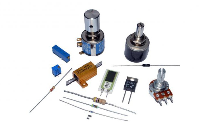
Having figured out what resistors are, it is necessary to consider their types, designation and marking.
Types of resistors
The types of resistors can be divided into the following categories:
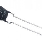
- Unregulated (permanent) - wire, composite, film, carbon, etc.
- Adjustable (variables and trimmers). Trimmer resistors are designed to tune electrical circuits. Elements with variable resistance (potentiometers) are used to adjust signal levels.
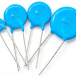
A separate group is represented by semiconductor resistive elements (thermistors, photoresistors, varistors, etc.)
The characteristics of resistors are determined by their purpose and are set during manufacture. Among the key parameters:
- Rated resistance. This is the main characteristic of the element, measured in ohms (Ohm, kOhm, MΩ).
- Allowable deviation as a percentage of the specified nominal resistance. Means the possible spread of the indicator, determined by the manufacturing technology.
- Power dissipation is the maximum power that a resistor can dissipate under long-term load.
- The temperature coefficient of resistance is a value showing the relative change in the resistance of a resistor with a temperature change of 1 ° C.
- Limit operating voltage (electrical strength). This is the maximum voltage at which the part retains the declared parameters.
- Noise characteristic - the degree of distortion introduced by the resistor into the signal.
- Moisture resistance and heat resistance - the maximum values of humidity and temperature, the excess of which can lead to failure of the part.
- Voltage factor. A value that takes into account the dependence of the resistance on the applied voltage.
The use of resistors in the microwave region gives importance to additional characteristics: parasitic capacitance and inductance.
Semiconductor resistors
These are semiconductor devices with two leads, which have a dependence of electrical resistance on the parameters of the environment - temperature, illumination, voltage, etc. For the manufacture of such parts, semiconductor materials doped with impurities are used, the type of which determines the dependence of conductivity on external influences.
There are the following types of semiconductor resistive elements:
- Line resistor. Made of a lightly alloyed material, this element has a low dependence of resistance on external influences in a wide range of voltages and currents; it is most often used in the production of integrated circuits.
- A varistor is an element whose resistance depends on the strength of the electric field. This property of the varistor determines the scope of its application: to stabilize and regulate the electrical parameters of devices, to protect against overvoltage, and for other purposes.
- Thermistor. This kind of non-linear resistive elements has the ability to change its resistance depending on temperature. There are two types of thermistors: the thermistor, whose resistance decreases with temperature, and thermistor, whose resistance increases with temperature. Thermistors are used where constant control over the temperature process is important.
- Photoresistor. The resistance of this device changes under the influence of a light flux and does not depend on the applied voltage.Lead and cadmium are used in the manufacture, in a number of countries this was the reason for refusing to use these parts for environmental reasons. Today, photoresistors are inferior in demand to photodiodes and phototransistors used in similar nodes.
- Strain gauge. This element is designed in such a way that it is able to change its resistance depending on external mechanical action (deformation). It is used in units that convert mechanical action into electrical signals.
Such semiconductor elements as linear resistors and varistors are characterized by a weak degree of dependence on external factors. For strain gauges, thermistors and photoresistors, the dependence of characteristics on the impact is strong.
Semiconductor resistors in the diagram are indicated by intuitive symbols.
Resistor in the circuit
On Russian circuits, elements with constant resistance are usually denoted as a white rectangle, sometimes with the letter R above it. On foreign circuits, you can find the designation of a resistor in the form of a “zigzag” icon with a similar letter R on top. If any parameter of the part is important for the operation of the device, it is customary to indicate it on the diagram.
Power can be indicated by stripes on a rectangle:
- 2 W - 2 vertical lines;
- 1 W - 1 vertical line;
- 0.5 W - 1 longitudinal line;
- 0.25 W - one oblique line;
- 0.125 W - two oblique lines.
It is permissible to indicate the power on the diagram in Roman numerals.
The designation of variable resistors is distinguished by the presence of an additional line with an arrow above the rectangle, symbolizing the possibility of adjustment, the numbers can indicate the pin numbering.
Semiconductor resistors are indicated by the same white rectangle, but crossed out with an oblique line (except for photoresistors) with a letter indicating the type of control action (U - for a varistor, P - for a strain gauge, t - for a thermistor). The photoresistor is indicated by a rectangle in a circle, towards which two arrows point, symbolizing light.
The parameters of the resistor do not depend on the frequency of the flowing current, which means that this element functions equally in DC and AC circuits (both low and high frequencies). An exception is wirewound resistors, which are inherently inductive and can lose energy due to radiation at high and microwave frequencies.
Depending on the requirements for the properties of the electrical circuit, resistors can be connected in parallel and in series. The formulas for calculating the total resistance for different circuit connections are significantly different. When connected in series, the total resistance is equal to the simple sum of the values of the elements included in the circuit: R \u003d R1 + R2 + ... + Rn.
When connected in parallel, to calculate the total resistance, it is necessary to add the reciprocals of the values of the elements. This will result in a value that is also the opposite of the final one: 1/R = 1/R1+ 1/R2 + ... 1/Rn.
The total resistance of resistors connected in parallel will be less than the smallest of them.
Denominations
There are standard resistance values for resistive elements, called the "nominal resistor range". The approach to creating this series is based on the following consideration: the step between the values should cover the allowable deviation (error). Example - if the value of the element is 100 ohms, and the tolerance is 10%, then the next value in the series will be 120 ohms.Such a step allows avoiding unnecessary values, since neighboring denominations, together with the error spread, practically cover the entire range of values between them.
Produced resistors are combined into series that differ in tolerances. Each series has its own nominal number.
Differences between series:
- E 6 - tolerance 20%;
- E 12 - tolerance 10%;
- E 24 - tolerance 5% (sometimes 2%);
- E 48 - tolerance 2%;
- E 96 - tolerance 1%;
- E 192 - 0.5% tolerance (sometimes 0.25%, 0.1% and lower).
The most widely used E 24 series includes 24 resistance values.
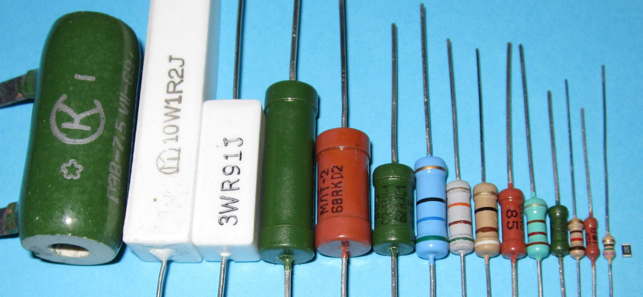
Marking
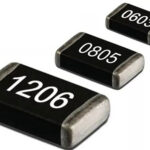
The size of the resistive element is directly related to its dissipation power, the higher it is, the larger the dimensions of the part. If it is easy to indicate any numerical value on the diagrams, then the marking of products can be difficult. The miniaturization trend in electronics manufacturing is driving the need for smaller and smaller components, which increases the complexity of both writing information on the package and reading it.
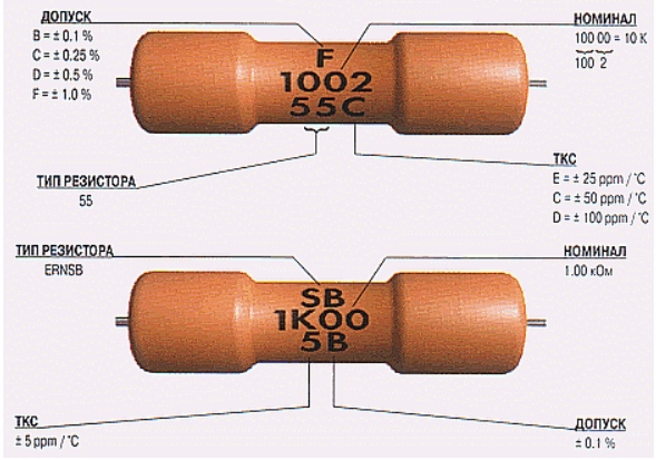
To facilitate the identification of resistors in the Russian industry, alphanumeric marking is used. Resistance is indicated as follows: the numbers indicate the denomination, and the letter is placed either behind the numbers (in the case of decimal values) or in front of them (for hundreds). If the value is less than 999 ohms, then the number is applied without a letter (or the letters R or E can stand). If the value is indicated in kOhm, then the letter K is put behind the number, the letter M corresponds to the value in MΩ.
The ratings of American resistors are indicated by three digits. The first two of them assume the denomination, the third - the number of zeros (tens) added to the value.
In the robotic production of electronic components, the applied symbols often end up on the side of the part that faces the board, which makes reading the information impossible.
Color coding
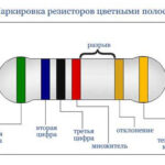
To ensure that information about the parameters of the part remains readable from any side, color marking is used, while the paint is applied in annular stripes. Each color has its own numerical value. The stripes on the details are placed closer to one of the conclusions and are read from left to right from it. If, due to the small size of the part, it is impossible to shift the color marking to one conclusion, then the first strip is made 2 times wider than the rest.
Elements with a permissible error of 20% are indicated by three lines, for an error of 5-10%, 4 lines are used. The most accurate resistors are indicated using 5-6 lines, the first 2 of them correspond to the part rating. If there are 4 lanes, then the third one indicates the decimal multiplier for the first two lanes, the fourth line means accuracy. If there are 5 bands, then the third of them is the third denomination, the fourth is the degree of the indicator (the number of zeros), and the fifth is the accuracy. The sixth line means the temperature coefficient of resistance (TCR).
In the case of a four-stripe marking, the gold or silver stripes always come last.
All signs look complicated, but the ability to quickly read the markings comes with experience.
Similar articles: