Switching processes are basic in all automated control systems. The most common switching elements in this case are intermediate electromagnetic relays.
Despite the large number of different semiconductor devices, electromagnetic relays are still used in all kinds of industrial equipment and household appliances. The popularity of relays is due to their reliability and high performance, which directly depend on the characteristics of metal contacts.
Content
What is a relay and where are they used?
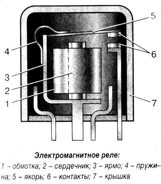
An electromagnetic relay is a high-precision and reliable switching device, the principle of which is based on the influence of an electromagnetic field. It has a simple structure, represented by the following elements:
- coil;
- anchor;
- fixed contacts.
The electromagnetic coil is fixed motionless on the base, inside it is a ferromagnetic core, a spring-loaded armature is attached to the yoke to return to its normal position when the relay is de-energized.
Simply put, the relay provides opening and closing of the electrical circuit in accordance with incoming commands.
Electromagnetic relays are reliable in operation, which is why they are used in various industrial and household electrical appliances and equipment.
Main types and technical characteristics of electromagnetic relays
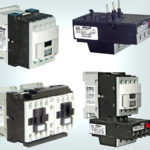
There are the following types:
- Current relay - according to its principle of operation, it practically does not differ from voltage relay. The fundamental difference lies only in the design of the electromagnetic coil. For a current relay, the coil is wound with a large cross-section wire, and contains a small number of turns, which is why it has a minimum resistance. The current relay can be connected through a transformer or directly to the contact network. In any case, it correctly controls the current strength in the controlled network, on the basis of which all switching processes are carried out.
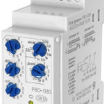
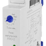
- Time relay (timers) - provides a time delay in control networks, necessary in some cases to turn on devices in accordance with a certain algorithm. Such relays have an extended range of settings necessary to ensure high accuracy of their operation. Each timer has separate requirements.For example, low consumption of electrical energy, small dimensions, high accuracy of work, the presence of powerful contacts, etc. It should be noted that for time relay, which are included in the design of the electric drive, additional increased requirements are not imposed. The main thing is that they have a solid design and have increased reliability, since they have to constantly function in conditions of increased loads.
Any of the types of electromagnetic relays has its own specific parameters. During the selection of the necessary elements, it is worth paying attention to the composition and properties of the contact pairs, to determine the nutritional features. Here are some of their main features:
- Trip voltage or current - the minimum value of the current or voltage at which the contact pairs of the electromagnetic relay are switched.
- Release voltage or current is the maximum value that controls the stroke of the armature.
- Sensitivity - the minimum amount of power required to operate the relay.
- winding resistance.
- Operating voltage and current strength are the values of these parameters necessary for the optimal operation of the electromagnetic relay.
- Operation time - the period of time from the start of power supply to the relay contacts until it is turned on.
- Release time - the period during which the armature of the electromagnetic relay will take its original position.
- Switching frequency - the number of times the electromagnetic relay is triggered in the allotted time interval.
Contact and non-contact
In accordance with the design features of the actuators, all electromagnetic relays are divided into two types:
- Contact - have a group of electrical contacts that ensure the operation of the element in the electrical network. Switching is carried out due to their closure or opening. They are universal relays, used in almost all types of automated electrical networks.
- Contactless - their main feature is the absence of actuating contact elements. The switching process is carried out by adjusting the parameters of voltage, resistance, capacitance and inductance.
By scope
Classification of electromagnetic relays according to the field of their use:
- control circuits;
- signaling;
- automatic emergency protection systems (PAZ, ESD).
According to the power of the control signal
All types of electromagnetic relays have a certain threshold of sensitivity; therefore, they are divided into three groups:
- low power (less than 1 W);
- medium power (up to 9 W);
- high power (more than 10 W).
By control speed
Any electromagnetic relay is distinguished by the speed of the control signal, and therefore they are divided into:
- adjustable;
- slow;
- high-speed;
- inertialess.
By type of control voltage
Relays are divided into the following categories:
- direct current (DC);
- alternating current (AC).
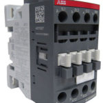
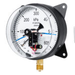
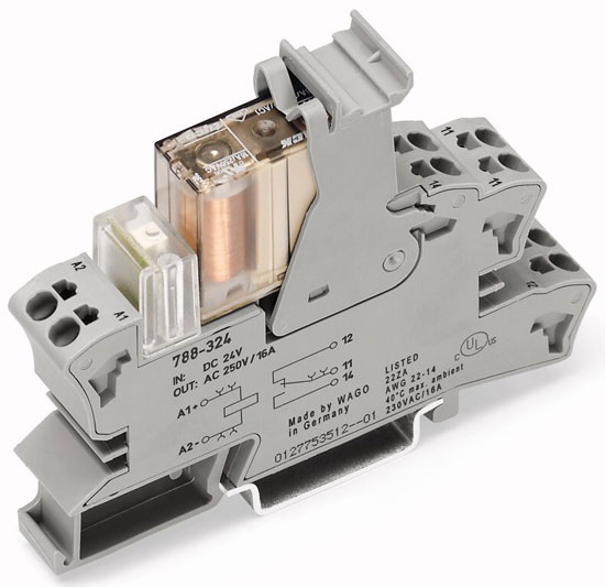
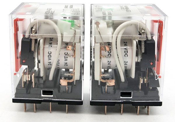
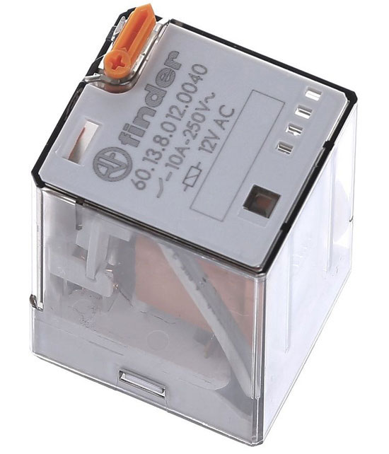
Note! The relay coil can be designed for an operating voltage of 24 V, but the relay contacts may well operate with voltages up to 220 V. This information is indicated on the relay housing.
The photo below shows that the coil indicates the operating voltage of 24 VDC, that is, 24 V DC.
According to the degree of protection from external factors
All electromagnetic relays have the following types of construction:
- open;
- sheathed;
- sealed.
Types of contact groups
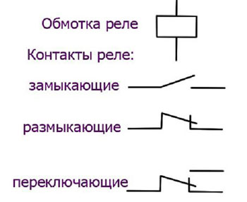
Electromagnetic relays have various configurations and design features of contact groups. We list the common types of elements:
- normally open (Normally Open - NO or Normally Open - NO) - their main feature is that the contact pairs are constantly in the open state, and they only work after applying voltage to the electromagnetic coil. As a result, the electrical circuit closes, the conductors begin to function in accordance with the specified algorithms.
- normally closed (Normally Closed - NC or Normally Closed - NC) - the contacts are in a permanently closed state and when the electromagnetic relay is energized (voltage is applied to the coil), they open.
- Changeover - this is a combination of normally closed and open contacts. There are three contacts, common, usually designated COM, closed to common and open to common. When voltage is applied to the coil, the NC contact opens and the NO contact closes.
Models of electromagnetic relays, in the design of which there are several contact groups, provide switching processes in several automated networks.
Note! Some types of relays have a manual contact switch. It can be useful when setting up the circuit. As well as an indication of the power supply of the relay coil.
Relay Wiring Diagram
On the cover of any device, the manufacturer applies a schematic diagram of connecting an electromagnetic relay to the network. On the wiring diagram the relay coil is represented by a rectangle and is denoted by the letter "TO" with a digital index, for example, K3. In this case, contact pairs that are not under load are marked with the letter "TO" with two digits separated by a dot. for example, K3.2 - contact number 2, relay K3. The designation is deciphered as follows: the first digit is the serial number of the electromagnetic relay in the diagram, the second indicates the index of the contact pairs of this relay.
Below is an example of an electrical circuit in which the solenoid of a pneumatic valve is controlled using the NO contact of relay K1. After closing S1, the relay is energized and the NO contact 13, 14 closes, while voltage appears on the solenoid Y1.
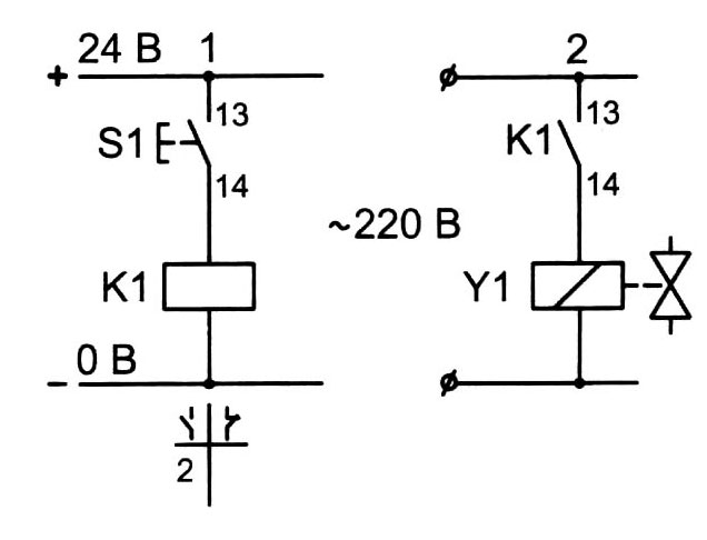
Contact pairs, which are located near the electromagnetic coil, marked with a dashed line. In the circuit diagram for connecting the relay, all parameters of the contact pairs are necessarily displayed, the maximum allowable value of the switching current of the contacts is indicated. On the relay coil, the manufacturer indicates the type of current and operating voltage.
It is worth noting that the electromagnetic relay connection diagram is drawn up for each type of element purely individually in accordance with the features of its operation in an automated network. At the same time, for the correct operation of some types of relays, a setting is required, during which the optimal parameters for the operation of the relay are set: activation delay, operation current, reboot, etc.
Similar articles: