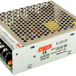
Alternating voltage is delivered from the power supply organization to consumers. This is due to the peculiarities of electricity transportation. But most household (and, in part, industrial) electrical receivers require constant voltage power. To get it, converters are required. In many cases, they are built according to the "step-down transformer - rectifier - smoothing filter" scheme (with the exception of switching power supplies). Diodes connected in a bridge circuit are used as a rectifier.
Content
What is a diode bridge for and how does it work
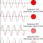
The diode bridge is used as a rectification circuit that converts AC voltage to DC. The principle of its operation is based on one-way conduction - the property of a semiconductor diode to pass current in only one direction.A single diode can also serve as the simplest rectifier.
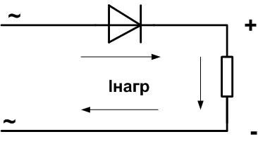
With such an inclusion, the lower (negative) part of the sinusoid is "cut off". This method has disadvantages:
- the shape of the output voltage is far from constant, a large and bulky capacitor is required as a smoothing filter;
- the AC power is used at a maximum of half.
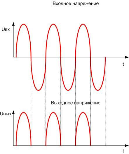
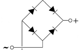
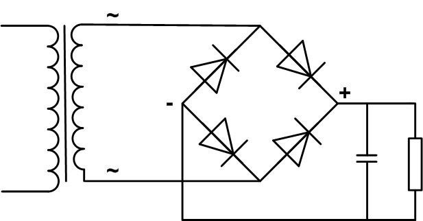
The current through the load follows the shape of the output voltage. Therefore, it is better to use a full-wave rectifier in the form of a diode bridge. If you turn on four diodes according to the indicated scheme and connect the load, then when an alternating voltage is applied to the input, the unit will work like this:
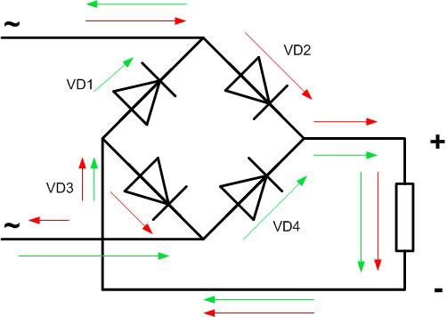
With a positive voltage (upper part of the sinusoid, red arrow), the current will flow through the VD2 diode, the load, VD3. With a negative (lower part of the sinusoid, green arrow) through the diode VD4, load, VD1. As a result, in one period, the current passes through the load twice in the same direction.
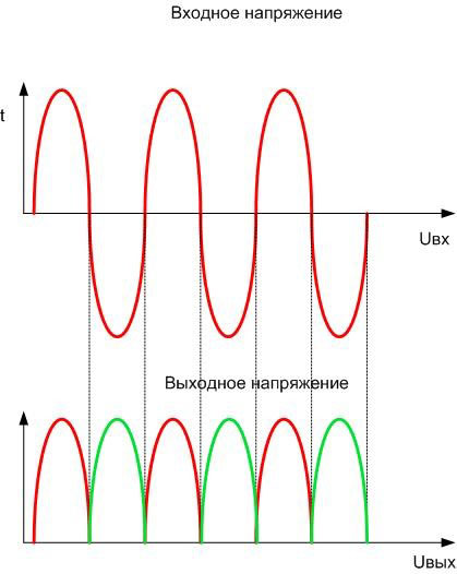
The output voltage waveform is much closer to a straight line, although the level of ripple is quite high. The source power is fully utilized.
If there is a source of three-phase voltage of the required amplitude, you can make a bridge according to the following scheme:
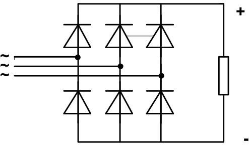
In it, three currents will be added to the load, repeating the shape of the output voltage, with a phase shift of 120 degrees:
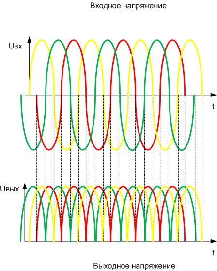
The output voltage will go around the tops of the sinusoids. It can be seen that the voltage pulsates much less than in a single-phase circuit, its shape is closer to a straight line. In this case, the capacitance of the smoothing filter will be minimal.
And another version of the bridge - controlled.In it, two diodes are replaced by thyristors - electronic devices that open when a signal is applied to the control electrode. In the open form, thyristors behave almost like ordinary diodes. The schema looks like this:
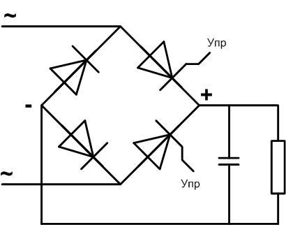
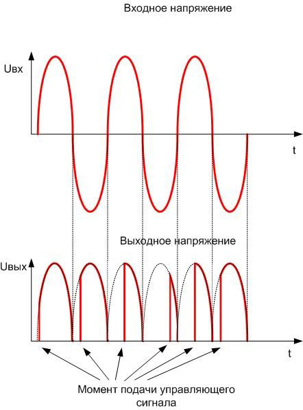
Switch-on signals are given from the control circuit at agreed times, shutdown occurs at the moment the voltage passes through zero. Then the voltage is averaged across the capacitor, and this average level can be controlled.
Diode bridge designation and connection diagram
Since a bridge of diodes can be built according to various schemes, and it contains few elements, in most cases the designation of a rectifier assembly is made by simply drawing its circuit diagram. If this is not acceptable - for example, in the case of building a block diagram - then the bridge is indicated as a symbol, which indicates any AC-to-DC converter:
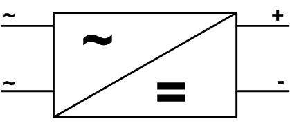
The letter "~" means chains alternating current, the symbol "=" - DC circuits, and "+" and "-" - the output polarity.
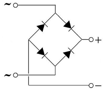
If the rectifier is built according to the classic bridge circuit of 4 diodes, then a slightly simplified image is allowed:
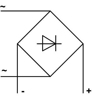
The input of the rectifier unit is connected to the output terminals of the AC source (in most cases it is a step-down transformer) without observing the polarity - any output terminal is connected to any input. The output of the bridge is connected to the load. It may or may not require polarity (including a stabilizer, smoothing filter).
The diode bridge can be connected to a constant voltage source.In this case, a protection circuit against unintentional polarity reversal is obtained - with any connection of the bridge inputs to the output of the power supply, the polarity of the voltage at its output will not change.
Main technical characteristics
When choosing diodes or a finished bridge, you first need to look at maximum operating forward current. It should exceed the load current with a margin. If this value is unknown, but the power is known, it must be converted into current according to the formula Iload \u003d Pload / Uout. To increase the allowable current, semiconductor devices can be connected in parallel - the largest load current is divided by the number of diodes. In this case, it is better to select diodes in one branch of the bridge according to a close value of the voltage drop in the open state.
The second important parameter is forward voltagefor which the bridge or its elements are designed. It must not be lower than the output voltage of the AC source (peak value!). For reliable operation of the device, you need to take a margin of 20-30%. To increase the allowable voltage, diodes can be connected in series - in each arm of the bridge.
These two parameters are enough for a preliminary decision on the use of diodes in a rectifier device, but some other characteristics should also be taken into account:
- maximum operating frequency - usually a few kilohertz and does not matter for operation at industrial frequencies of 50 or 100 Hz, and if the diode operates in a pulse circuit, this parameter can become decisive;
- on-state voltage drop for silicon diodes it is about 0.6 V, which is unimportant for an output voltage of, for example, 36 V, but can be critical when operating below 5 V - in this case, Schottky diodes should be chosen, which are characterized by a low value of this parameter.
Varieties of diode bridges and their marking
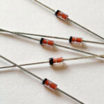
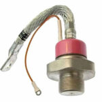
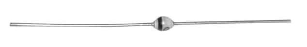
The diode bridge can be assembled on discrete diodes. To observe the polarity, you need to pay attention to the markings. In some cases, a mark in the form of a pattern is applied directly to the body of the semiconductor device. This is typical for domestic products.
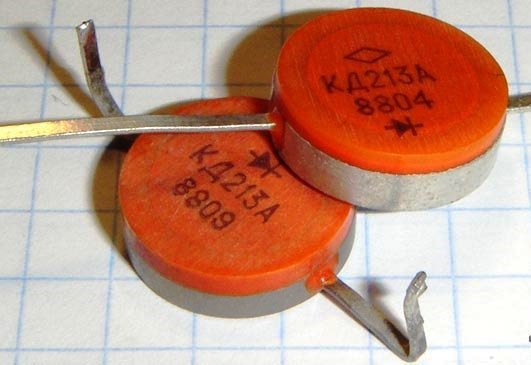
Foreign (and many modern Russian) devices are marked with a dot or a ring. In most cases, this is the designation of the anode, but there is no guarantee. It is better to look at the manual or use the tester.
You can make a bridge from the assembly - four diodes are combined in one package, and the connection of the leads can be done with external conductors (for example, on a printed circuit board). Assembly schemes can be varied, so for the correct connection, you need to look at the datasheets.
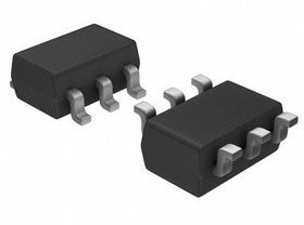
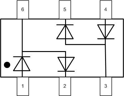
For example, the BAV99S diode assembly, containing 4 diodes but having only 6 pins, has two half-bridges inside, connected as follows (there is a dot on the case near pin 1):
To get a full-fledged bridge, it is necessary to connect the corresponding outputs with external conductors (the trace of the tracks is shown in red in the case of using printed wiring):
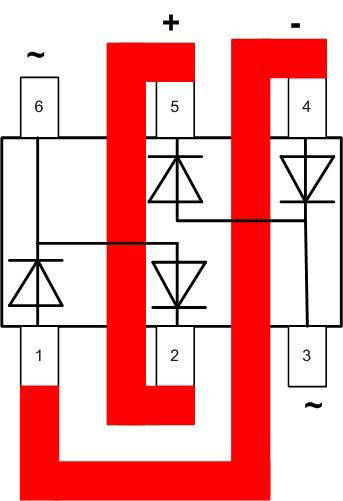
In this case, an alternating voltage is applied to pins 3 and 6. The positive pole of the constant is removed from pin 5 or 2, and the negative pole - 4 or 1.
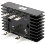
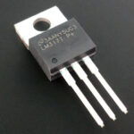
And the easiest option is to assemble with a ready-made bridge inside.Of domestic products, these can be KTs402, KTs405, there are assembly bridges of foreign production. In many cases, the marking of the conclusions is applied directly to the case, and the task is reduced only to the correct choice according to the characteristics and to the error-free connection. If there is no external designation of the conclusions, you will have to refer to the directory.
Advantages and disadvantages
The advantages of a diode bridge are well known:
- schemes worked out for decades;
- ease of assembly and connection;
- simple fault diagnosis and easy repair.
As disadvantages, it is necessary to mention the increase in the dimensions and weight of the circuit with increasing power, as well as the need to use heat sinks for high-power diodes. But nothing can be done about it - physics cannot be deceived. When these conditions become unacceptable, it is necessary to decide on the transition to a pulsed power supply circuit. By the way, bridging diodes can be used in it.
It should also be noted that the shape of the output voltage is far from constant. To work with consumers who place demands on the stability of the supply voltage, it is necessary to use a bridge in conjunction with smoothing filters, and, if necessary, output stabilizers.
Similar articles: