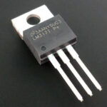
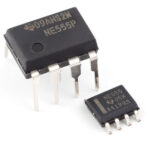
KREN, “roll” is the common name for integrated voltage stabilizers of the 142 series. The dimensions of its case do not allow the full marking of the series (KR142EN5A, etc.), so the developers limited themselves to a short version - KREN5A. "Krenki" are widely used both in industry and in amateur practice.
Content
What are voltage stabilizers KREN 142
Microcircuits of the 142 series have gained popularity due to the ease of obtaining a stable voltage - simple binding, no adjustments and settings. It is enough to apply power to the input, and get a stabilized voltage at the output. The most famous and widespread are unregulated integrated stabilizers in TO-220 cases for voltages up to 15 volts:
- KR142EN5A, V - 5 volts;
- KR142EN5B, G - 6 volts;
- KR142EN8A, G - 9 volts;
- KR142EN8B, D - 12 volts;
- KR142 EN8V, E - 15 volts;
- KR142 EN8Zh, I - 12.8 volts.
In cases where it is necessary to obtain a higher stable voltage, devices are used:
- KR142EN9A - 20 volts;
- KR42EN9B - 24 volts;
- KR142EN9V - 27 volts.
These microcircuits are also available in planar design with slightly different electrical characteristics.
Series 142 includes other integral stabilizers. To microchips with adjustable output voltage relate:
- KR142EN1A, B - with control limits from 3 to 12 volts;
- KR142EN2B - with limits of 12 ... 30 volts.
These devices are available in 14-pin packages. This category also includes three-terminal stabilizers with the same output range of 1.2 - 37 volts:
- KR142EN12 positive polarity;
- KR142EN18 negative polarity.
The series includes the KR142EN6 chip - a bipolar stabilizer with the ability to adjust the output voltage from 5 to 15 volts, as well as switching on as an unregulated source of ± 15 volts.
All elements of the series have built-in protection against overheating and short circuit at the output. And they do not like polarity reversal at the input and the supply of external voltage to the output - the lifetime in such cases is calculated in seconds.
Chip modifications
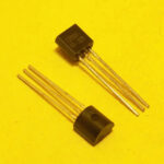
Modifications of microcircuits included in the series differ in case. Most unipolar unregulated stabilizers are made in the TO-220 "transistor" package. It has three conclusions, this is not enough in all cases. Therefore, some microcircuits were produced in multi-output packages:
- DIP-14;
- 4-2 - the same, but in a ceramic shell;
- 16-15.01 - planar housing for surface mounting (SMD).
In such versions, mainly adjustable and bipolar stabilizers are produced.
Main technical characteristics
In addition to the output voltage, the current that it can provide under load is important for the stabilizer.
| Chip type | Rated current, A |
|---|---|
| K(R)142EN1(2) | 0,15 |
| K142EN5A, 142EN5A | 3 |
| KR142EN5A | 2 |
| K142EN5B, 142EN5B | 3 |
| KR142EN5A | 2 |
| K142EN5V, 142EN5V, KR142EN5V | 2 |
| K142EN5G, 142EN5G, KR142EN5G | 2 |
| K142EN8A, 142EN8A, KR142EN8A | 1,5 |
| K142EN8B, 142EN8B, KR142EN8B | 1,5 |
| K142EN8V, 142EN8V, KR142EN8V | 1,5 |
| KR142EN8G | 1 |
| KR142EN8D | 1 |
| KR142EN8E | 1 |
| KR142EN8Zh | 1,5 |
| KR142EN8I | 1 |
| K142EN9A, 142EN9A | 1,5 |
| K142EN9B, 142EN9B | 1,5 |
| K142EN9V, 142EN9V | 1,5 |
| KR142EN18 | 1,5 |
| KR142EN12 | 1,5 |
These data are sufficient for a preliminary decision on the possibility of using one or another stabilizer. If you need additional specifications, they can be found in reference books or on the Internet.
Purpose of conclusions and principle of operation
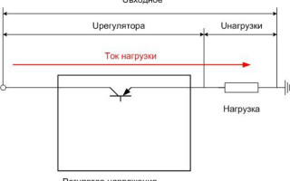
According to the principle of operation, all microcircuits of the series belong to linear regulators. This means that the input voltage is distributed between the regulating element (transistor) of the stabilizer and the load so that the voltage drops across the load, which is set by the internal elements of the microcircuit or external circuits.
If the input voltage increases, the transistor turns off; if it decreases, it opens slightly so that the output voltage remains constant. When the load current changes, the stabilizer works in the same way, maintaining the load voltage unchanged.
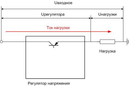
This scheme has disadvantages:
- The load current constantly flows through the control element, so the power P=U is constantly dissipated on it.regulator⋅Iloads. This power is wasted and limits the efficiency of the system - it cannot be higher than Uloads/uregulator.
- The input voltage must exceed the stabilization voltage.
But the ease of use, the low cost of the device outweigh the disadvantages, and in the range of operating currents up to 3 A (and even higher) something more complex to apply is meaningless.
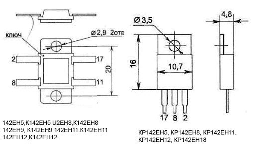
For voltage regulators with a fixed voltage, as well as for adjustable stabilizers of new developments (K142EN12, K142EN18) in three- and four-pin versions, the conclusions are indicated by the numbers 17.8.2. Such an illogical combination was chosen, obviously, to match the pins with microcircuits in DIP packages. In fact, such a "dense" marking was preserved only in the technical documentation, and on the diagrams they use the designations of the conclusions corresponding to foreign analogues.
| Designation according to technical documentation | Designation on the diagrams | Output Destination | ||
|---|---|---|---|---|
| Fixed Voltage Stabilizer | Voltage Regulated Stabilizer | Fixed Voltage Stabilizer | Voltage Regulated Stabilizer | |
| 17 | In | Entrance | ||
| 8 | GND | ADJ | common wire | Reference voltage |
| 2 | out | Exit | ||
Chips of the old design K142EN1 (2) in 16-pin planar packages have the following pin assignment:
| Purpose | Output number | Output number | Purpose |
|---|---|---|---|
| Not used | 1 | 16 | Input 2 |
| Noise filter | 2 | 15 | Not used |
| Not used | 3 | 14 | Exit |
| Entrance | 4 | 13 | Exit |
| Not used | 5 | 12 | Voltage regulation |
| Reference voltage | 6 | 11 | current protection |
| Not used | 7 | 10 | current protection |
| General | 8 | 9 | Shutdown |
The disadvantage of the planar design is a large number of redundant leads of the device.
KR142EN1(2) stabilizers in DIP14 packages have a different pin assignment.
| Purpose | Output number | Output number | Purpose |
|---|---|---|---|
| current protection | 1 | 14 | Shutdown |
| current protection | 2 | 13 | Correction circuits |
| Feedback | 3 | 12 | Input 1 |
| Entrance | 4 | 11 | Input 2 |
| Reference voltage | 5 | 10 | Exit 2 |
| Not used | 6 | 9 | Not used |
| General | 7 | 8 | Exit 1 |
The K142EN6 and KR142EN6 microcircuits, produced in different package options with a heat sink and a single-row pinout, have the following pinout:
| Output number | Purpose |
|---|---|
| 1 | Both arm adjustment signal input |
| 2 | Exit "-" |
| 3 | Entrance "-" |
| 4 | General |
| 5 | Correction "+" |
| 6 | Not used |
| 7 | Exit "+" |
| 8 | Input "+" |
| 9 | Correction "-" |
An example of a typical connection diagram
For all unregulated unipolar stabilizers, the typical circuit is the same:
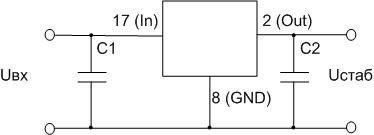
C1 should have a capacitance of 0.33 uF, C2 - from 0.1. As C1, the filtering capacitor of the rectifier can be used if the conductors from it to the input of the stabilizer have a length of no more than 70 mm.
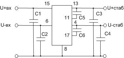
The bipolar stabilizer K142EN6 is usually turned on like this:
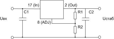
For K142EN12 and EH18 microcircuits, the output voltage is set by resistors R1 and R2.
For K142EN1 (2), a typical switching circuit looks more complicated:
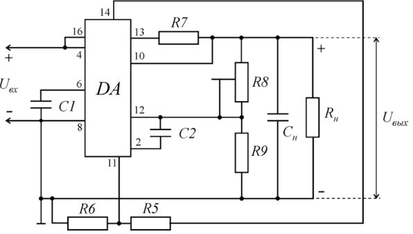
In addition to typical switching circuits, integrated circuits for stabilizers of the 142 series, there are other options that allow you to expand the scope of microcircuits.
What are the analogues
For some devices of the 142 series, there are complete foreign analogues:
| Chip K142 | Foreign analogue |
|---|---|
| ROLL12 | LM317 |
| ROLL18 | LM337 |
| KREN5A | (LM)7805C |
| KREN5B | (LM)7805C |
| KREN8A | (LM)7806C |
| KREN8B | (LM)7809C |
| KREN8V | (LM)78012C |
| ROLL6 | (LM)78015C |
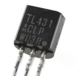
| KREN2B | UA723C |
Full analog means that the microcircuits are the same in electrical characteristics, in case and pinout. But there are also functional analogues, which in many cases replace the design chip.So, 142EN5A in a planar package is not a complete analogue of 7805, but it corresponds to it in terms of characteristics. Therefore, if it is possible to install one housing instead of another, then such a replacement will not impair the quality of the entire device.
Another situation - KREN8G in the "transistor" version is not considered an analogue of 7809 due to the fact that it has a lower stabilization current (1 ampere versus 1.5). If this is not critical and the actual current consumed in the power circuit is less than 1 A (with a margin), then you can safely change the LM7809 to KR142EN8G. And in each specific case, you should always resort to the help of a reference book - you can often pick up something similar in functionality.
How to check the performance of KREN microcircuits
The 142 series microcircuits have a rather complicated device, so it is impossible to unequivocally check its performance with a multimeter. The only way is to assemble a real turn-on breadboard (on a board or surface-mounted), which includes at least the input and output capacitances, apply power to the input and check the voltage at the output. It must match the passport.
Despite the dominance of foreign-made microcircuits on the market, the 142 series devices hold their positions due to the quality of workmanship and other consumer properties.
Similar articles: