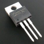
When designing electronic circuits, there is often a need for a low-power voltage regulator or a reference voltage source. A number of fixed voltages are closed by unregulated integral stabilizers. Adjustable build on chip LM317, but it has certain inherent flaws and often unnecessary functionality. In many cases, the TL431 chip will solve the problem, allowing you to get a low-power stable voltage source that can be adjusted from 2.5 to 36 V.
Content
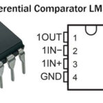
What is the TL431 chip
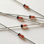
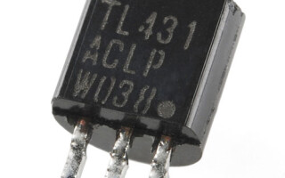
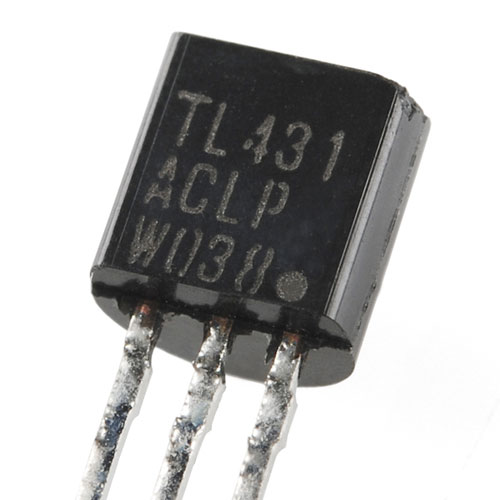
This microcircuit, developed in the 70s of the twentieth century, is often called an "adjustable zener diode", and is designated on the diagram as a zener diode with two classical conclusions - an anode and a cathode. There is also a third conclusion, the purpose of which will be discussed later. Looks like a micro-assembly zener diode doesn't recall at all. It is produced, like a conventional microcircuit, in several package options. Initially, options were made only for a board with holes (true hole), with the development of SMD technologies, TL431 began to be “packed” into surface-mounted packages, including popular SOTs with a different number of pins. The minimum number of legs required for operation is 3. Some cases contain more pins. Excess legs are either not connected anywhere, or duplicated.
Key Features of TL431
The main characteristics, the knowledge of which is sufficient to perform 90+ percent of the tasks that arise in the development of electronic circuits:
- output voltage limits - 2.5 ... 36 V (this can be attributed to the minuses, since modern regulators have a lower limit of 1.5 V);
- the highest current is 100 mA (it is small, comparable to a medium power zener diode, so you should not overload the microcircuit, it has no protection);
- internal resistance (impedance of an equivalent two-terminal network) - about 0.22 Ohm;
- dynamic resistance - 0.2 ... 0.5 Ohm;
- passport value Uref = 2.495 V, accuracy - depending on the series, from ± 0.5% to ± 2%;
- operating temperature range for TL431С – 0…+70 °С, for TL431A – minus 40…+85 °С.
Other characteristics, including graphs of the dependence of parameters on temperature, can be found in the datasheet. But in most cases they won't be needed.
Purpose of conclusions and principle of operation
When analyzing the internal structure of the microcircuit, it becomes clear that the comparison with the zener diode is rather arbitrary.
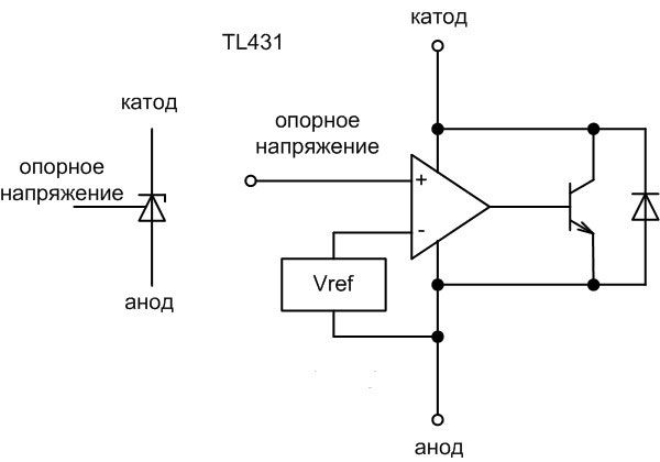
Most of all, the structure of the TL431 resembles a comparator. A reference voltage Vref of 2.5 V is applied to the inverting output.This voltage is stabilized, so the output will also be stable. The non-inverting output is brought out. If the voltage applied to it does not exceed the reference voltage, comparator output zero, the transistor is closed, no current flows. If the voltage at the direct input exceeds 2.5 V, then a positive level appears at the output of the differential amplifier, the transistor opens, and current begins to flow through it. This current is limited by external resistance. This behavior resembles the avalanche breakdown of a zener diode when a reverse voltage is applied to it. The diode is designed to protect against reverse switching on of the microcircuit.
Important! The voltage reference pin must not be left unconnected, it requires a current of at least 4 µA.
In fact, this scheme is conditional - it is suitable only for explaining the nature of the work. In reality, everything is implemented according to other principles. So, inside the circuit you can not find a point with a reference voltage of 2.5 V.
Examples of switching circuits
One of the options for the TL431 switching circuit is a conventional comparator. You can build some kind of threshold relays on it - for example, a level relay, a lighting relay, etc. Only the reference voltage source is built-in and cannot be adjusted, therefore, the current and voltage drop through the sensor are regulated.
As soon as 2.5 V drops on the sensor, the output transistor of the microcircuit opens, current flows through the LED and it lights up. Instead of LED, you can use a low-power relay or a transistor switch that switches the load. Resistor R1 can be used to adjust the level of operation of the comparator. R2 serves as a ballast and limits the current through the LED.
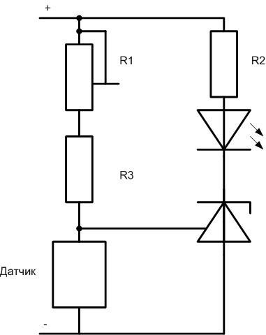
But such an inclusion does not make it possible to use all the features of the TL431 - the comparator can be built on any other microcircuit that is more suitable for such relays.The same assembly is designed for other purposes.
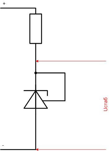
The simplest circuit for switching on the TL431 in parallel regulator mode is a 2.5 V reference voltage source. For this, only a ballast is needed resistor, which will limit the current through the output transistor.
Important! Unlike the classic zener diode switching circuit, you should not install a capacitor in parallel with the output. This can lead to parasitic oscillations. In general, it is not needed, since the developers have taken measures to reduce output noise. But because of this, the microcircuit cannot be used as the basis for a noise generator, like a conventional zener diode.
More fully the capabilities of the microcircuit are used in a feedback circuit formed by resistors R1 and R2.
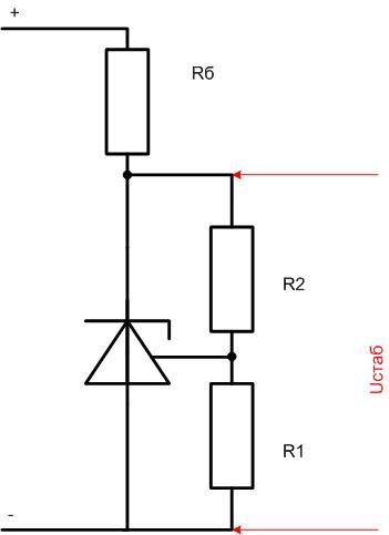
When power is applied, the output voltage rises and stabilizes within a few microseconds (slew rate is not standardized). Ustab is set divider, it can be calculated by the formula Ustab=2.495*(1+R2/R1). When calculating, it must be borne in mind that the internal resistance with such an inclusion increases by (1 + R2 / R1) times.
You can increase the load capacity of the stabilizer in the classical way by turning on an additional bipolar transistor.
Important! The transistor is necessarily included in the feedback loop circuit.
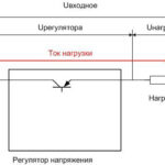
Such an inclusion converts the circuit into a parallel regulator, requiring the input voltage to exceed the output voltage. Its efficiency cannot exceed the Uout/Uin ratio. This worsens the parameters of the stabilizer, so it is better to use a field-effect transistor, the voltage drop on it is less.
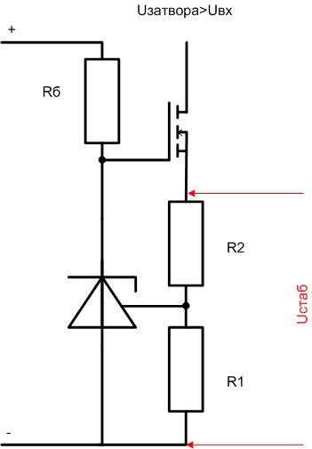
Here, the efficiency is higher due to the smaller required difference between the input and output voltage, but an additional power source is needed for the transistor gate - its voltage must exceed Vin.
On TL431, you can assemble a current stabilizer.
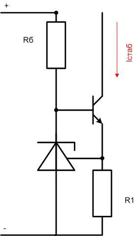
The current in the collector circuit of the transistor will be equal to Istab \u003d Vref / R1.
If the same circuit is included in the form of a two-terminal network, then a current limiter will be obtained.
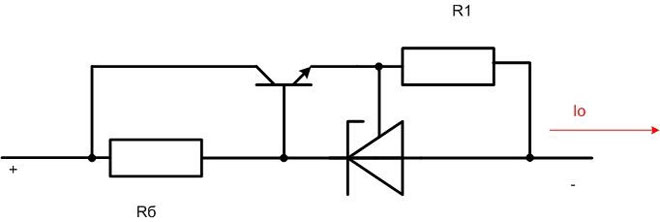
The current will be limited to Io=Vref/R1+Ika. The value of the ballast resistor must be selected from the conditions Rb=Uin(Io/hfe+Ika), where hfe is the transistor gain. It can be measured with a multimeter that has this function.
Radio amateurs use microcircuits in non-standard inclusions. TL431 has a tendency to self-excite, which is a disadvantage. But this makes it possible to use it as voltage-controlled generators. To do this, a capacitor is installed at the output.
What are the analogues
The microcircuit has a high popularity in the world of professionals and electronics enthusiasts. Therefore, it is produced by many manufacturers. The world-famous companies Texas Instruments (as a developer), Motorola, Fairchild Semiconductor and others produce a microcircuit under the original name. It is impossible not to mention the previously released TL430 stabilizer, with Vref = 2.75 V and a maximum operating current increased by one and a half times. But this microcircuit was less in demand, and did not live up to the beginning of the era of SMD mounting.
Other manufacturers produce a voltage regulator with other letter indices, but they always have the numbers 431 in their names (otherwise the consumer simply will not pay attention to the unknown microcircuit). On the market are:
- KA431AZ;
- KIA431;
- HA17431VP;
- IR9431N
and other microcircuits similar in functionality. But products of little-known and unknown manufacturers do not guarantee compliance with the parameters.
There is a domestic analogue - KR142EN19A, produced in the KT-26 package (similar to a low power transistor). It is completely similar to the original chip, but some characteristics are slightly different. So, the internal resistance is normalized within <0.5 Ohm.
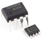
Worth mentioning is the SG6105 PWM controller. It contains two internal stabilizers, absolutely identical to the TL431. They have separate terminals and can be used as reference voltage sources.
How to check the performance of the TL431 chip
The microcircuit has a rather complex internal structure, so it cannot be checked by one tester. In any case, you will have to collect some kind of scheme. If there is a regulated power supply, then three resistors and an LED are required.
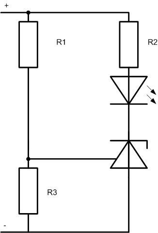
The voltage of the power supply must be no more than 36 V. R1 is chosen so that at the maximum voltage, the current through the LED does not exceed 10-15 mA. The ratio of R1 and R3 should be such that at the maximum source voltage, more than 2.5 V falls on R3, and preferably more than 3. When the output voltage rises from 0 V to reach the threshold on R3, the LED will flash, which means the microcircuit is working. You can not install the LED, but simply measure the voltage at the cathode - it should change abruptly.
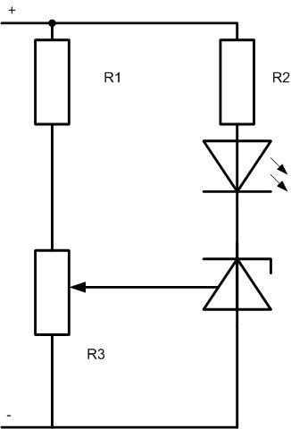
If there is no regulated source, but there is a power supply with a constant voltage, you will have to use a potentiometer instead of R3. When the engine rotates in both directions, the LED should light up and go out.
The electronic components market offers a very wide range of integrated voltage regulators.But the scope is very extensive, so many types of microcircuits have their niche in the market. Including TL431.
Similar articles: