Capacitance is a measure of the ability of a capacitor to store charges. Capacitance is measured in farads, named after an honorary member of St. Petersburg University, English physicist Michael Faraday.
Content
What is capacity?
If you remove a single electrical conductor infinitely far away, exclude the influence of charged bodies on each other, then the potential of the remote conductor will become proportional to the charge. But for conductors that differ in size, the potentials do not match.
The SI unit of capacitance for a capacitor is the farad. The proportionality factor is denoted by the letter C - this is the capacitance, which is affected by the size and external structure of the conductor. The material, the phase state of the substance of the electrode does not play a role - the charges are distributed on the surface. Therefore, in the international CGS rules, capacitance is measured not in farads, but in centimeters.
A solitary ball with a radius of 9 million km (1400 Earth radii) contains 1 farad.A separate conductive element holds charges in insufficient quantities for use in technology. Technology of the 21st century capacitance of capacitors with units of measurements above 1 farad is created.
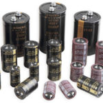
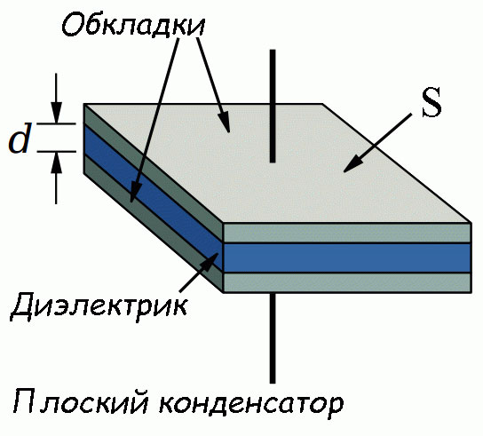
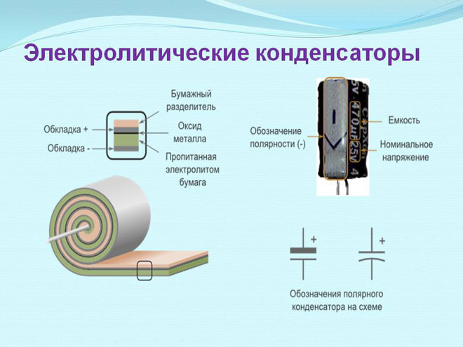
A structure of at least 2 electrodes and a separating dielectric is capable of accumulating the amount of electricity required for the operation of electronic circuits. In such a design, positive and negative particles are mutually attracted and hold themselves. The dielectric between the electron-positron pair does not allow annihilation. This state of charge is called bound.
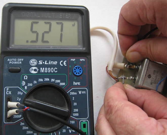
Previously, bulky equipment that did not differ in accuracy was used to measure electrical quantities. Now, even a novice radio amateur knows how to measure the capacitance with a tester.
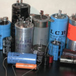
Capacitor markings
Knowing the characteristics of electronic devices is required for accurate and safe operation.
Determining the capacitance of a capacitor includes measuring the value with instruments and reading the markings on the case. The indicated values and those obtained during measurements differ. This is due to the imperfection of production technologies and the operational variation of parameters (wear, temperature effects).
The nominal capacitance and tolerance parameters are indicated on the case. In household appliances, devices with a deviation of up to 20% are used. In the space industry, military equipment and automation of dangerous objects, a spread of characteristics of 5-10% is allowed. Work diagrams do not contain tolerance values.
The nominal capacity is coded according to IEC standards - the International Electrotechnical Commission, which brings together national organizations according to the standards of 60 countries.
The IEC standard uses the notation:
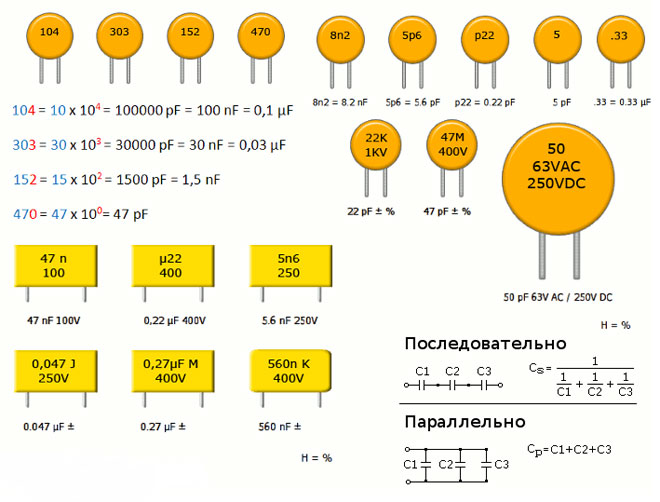
- 3 digit encoding. 2 characters at the beginning - the number of pF, the third - the number of zeros, 9 at the end - the value is less than 10 pF, 0 in front - no more than 1 pF. Code 689 - 6.8 pF, 152 - 1500 pF, 333 - 33000 pF or 33 nF, or 0.033 uF. For ease of reading, the decimal point in the code is replaced by the letter "R". R8 \u003d 0.8 pF, 2R5 - 2.5 pF.
- 4 digits in the marking. The last one is the number of zeros. 3 first - value in pF. 3353 - 335000pF, 335nF or 0.335uF.
- Using letters in code. The letter µ is uF, n is nanofarad, p is pF. 34p5 - 34.5 pF, 1µ5 - 1.5 µF.
- Glider ceramic products are coded with the letters A-Z in 2 registers and a number indicating the power of 10. K3 - 2400 pF.
- Electrolytic SMD devices are marked in 2 ways: numbers - rated capacitance in pF and next to or in 2 lines if there is space - the value of the rated voltage; the letter encoding the voltage and next to 3 digits, 2 determine the capacitance, and the last - the number of zeros. A205 means 10V and 2uF.
- Surface mount products are marked with a code of letters and numbers: CA7 - 10 microfarads and 16 V.
- Encodings - body color.
IEC markings, national designations and brand codes make memorizing codes meaningless. Hardware designers and repairmen require reference sources.
Formula calculation
The calculation of the nominal capacity of the element is required in 2 cases:
- Designers of electronic equipment calculate the parameter when creating circuits.
- Masters in the absence of capacitors of suitable power and capacity use the calculation of the element to select from the available parts.
RC circuits are calculated using the impedance value - complex resistance (Z). Ra is the current loss for heating the circuit participants. Ri and Re - take into account the influence of the inductance and capacitance of the elements. At the terminals of the resistor in the RC circuit, the voltage Ur is inversely proportional to Z.
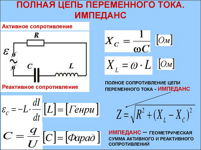
Thermal resistance increases the potential at the load, and reactive reduces it. The operation of the capacitor at frequencies above resonant, when the reactive component of the complex resistance increases, leads to voltage losses.
The resonance frequency is inversely proportional to the ability to store charge. From the formula for determining Fp, it is calculated what values of Sk (capacitor capacitance) are required for the operation of the circuit.
To calculate pulse circuits, the circuit time constant is used, which determines the effect of RC on the pulse structure. If the circuit resistance and the charge time of the capacitor are known, the capacitance is calculated using the time constant formula. The truth of the result is influenced by the human factor.
Masters use parallel and series connections of capacitors. The calculation formulas are inverse to the formulas for resistors.
A series connection makes the capacitance smaller in the connection of elements, a parallel circuit sums up the values.
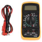
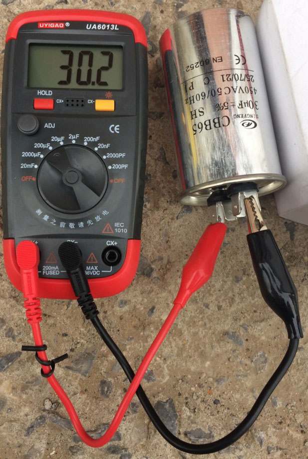
How to measure the capacitance of a capacitor with a multimeter?
When measuring parameters, the capacitor is preliminarily discharged by closing the leads with a screwdriver with insulation on the handle. If this is not done, the low-power multimeter will fail.
The answer to the question of how to check the capacitance of a capacitor with a multimeter with the "Cx" mode is as follows:
- Turn on the "Cx" mode and select the measurement limit - 2000 pF - 20 μF in a standard device;
- Insert the capacitor into the sockets in the device or attach the probes to the terminals of the capacitor and look at the value on the scale of the device.
An amperovoltmeter or multimeter determines the presence of a short circuit or open circuit inside the case.
A polar capacitor is included in the circuit of the device, taking into account the direction of the current. Manufacturers mark the electrodes of the product. A capacitor designed for a voltage of 1-3 V will fail if the reverse current is higher than normal.
Before measuring the characteristics, the polar electrolytic capacitor is unsoldered from the board. Turn on the multimeter to measure resistance or test semiconductors. Apply the probes to the electrodes of the polar capacitor - plus to plus, minus to minus. A good capacitance will show a smooth increase in resistance. As the charge current decreases, the EMF increases and reaches the voltage of the power source.
An open in the capacitor will look like an infinite resistance on the multimeter. The device will not respond or the pointer on the analog copy will barely move.
When the element breaks down, the measured parameter does not correspond to the nominal value in the lower direction, in proportion to the breakdown value.
If you ask yourself how to measure the complex or equivalent series resistance (ESR of a capacitor) with a multimeter, then it is problematic to do this without a prefix. The capacitor exhibits reactive properties at high-frequency current.
Other measurement methods
Do-it-yourself capacitor capacitance meter is assembled according to the schemes of pulse devices. Sequences of RC circuits with variable resistors create a series of signals at the output of the product with a step change in frequency. To set up the device, use a multimeter with which the prefix will be used.
A set of tested capacitors is connected in turn to the structure and the accuracy of operation is adjusted in each subrange.
A do-it-yourself capacitance meter for polar electrolytic cells is schematically implemented and configured as part of a prefix without an oscillatory circuit. At the output, instead of a pulsed voltage, there is a constant voltage.
In digital capacitance meters, the power supply is highly stable. "Floating" parameters of the elements from which the circuit is assembled will give an error that is unacceptable for measurement accuracy.
On logic elements, sources of alternating pulsed current are created for measuring ESR.
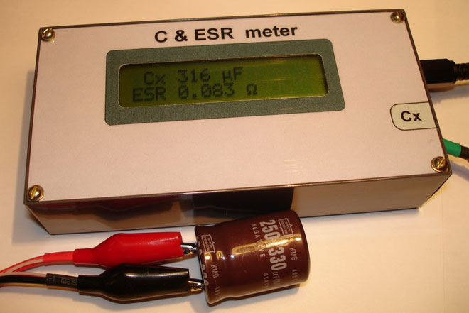
Inexpensive capacitor capacitance meters, such as RLC bridge devices with an additional SMD resistance test function, mains charging and an LCD display, are themselves the size of a finger. They perform the functions of a professional metrological complex. Able to act as a capacitance meter for electrolytic capacitors, both polar and variable.
Similar articles: