When developing electrical circuits, it often becomes necessary to use voltage stabilizers of low or medium power (up to 1.5 A) or reference voltage sources. It is convenient if such a node is available in an integrated design, in the form of a single microcircuit. A range of 9 DC voltage ratings ranging from 5V to 24V close the series regulators 78XX. Niche work LM317 - voltages are higher (up to 37 V) and below (up to 1.2 V) of this range, intermediate voltage values, adjustable stabilizers.
Content
What is the LM317 chip
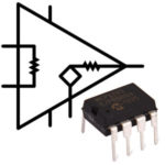
The microcircuit is a linear voltage regulator, the output value of which can be set within certain limits or quickly adjusted. Available in several housing options with three leads.The output voltage range for all options is the same, and the maximum current may vary.
| Designation | Maximum current, A | Frame |
|---|---|---|
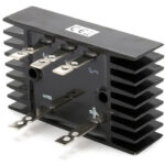
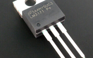
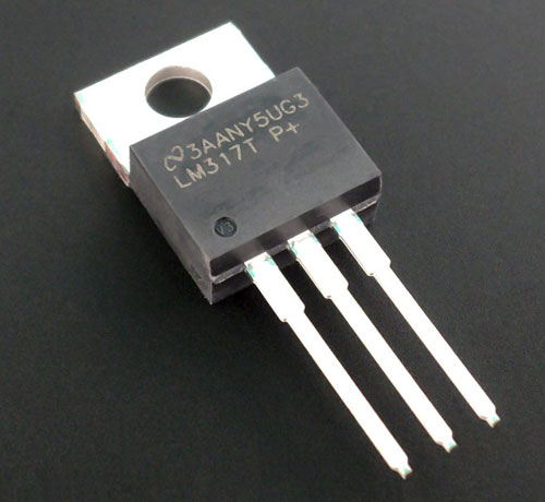
| LM317T | 1,5 | TO-220 |
| LM317LZ | 0,1 | TO-92 |
| LM317P | 1,5 | ISOWAT-220 |
| LM317D2T | 1,5 | D2PAK |
| LM317K | 0,1 | TO-3 |
| LM317LD | 1,5 | SO-8 |
Key Features of LM317 Linear Voltage Regulator
The datasheets for the LM317 stabilizer contain full technical information, which can be found by studying the specification. Below are the parameters, the non-compliance with which is the most critical and if used incorrectly, the microcircuit may fail. First of all, this is the maximum operating current. It is given in the previous section for different types of execution. It must be added that in order to obtain the maximum current of 1.5 A, the microcircuit must be installed on a heat sink.
The maximum voltage at the output of the regulator, built on the basis of the LM317, can be no more than 40 V. If this is not enough, you must choose a high-voltage analogue of the stabilizer.
The minimum output voltage is 1.25 V. With this circuit design, you can get less, but overload protection will work. This is not the best option - such protection should work against exceeding the output current, as it works in other integrated stabilizers. Therefore, in practice, it is impossible to get a regulator that works from zero when a negative bias is applied to the Adjust pin.
The minimum value of the input voltage is not indicated in the datasheet, but can be determined from the following considerations:
- minimum output voltage - 1.25 V;
- the minimum voltage drop for Uout = 37 V is equal to three volts, it is logical to assume that for the minimum output it should be no less;
Based on these two premises, at least 3.5 V must be applied to the input to obtain the minimum output value. Also, for stable operation, the current through the divider must be at least 5 mA - so that the parasitic current of the ADJ output does not introduce a significant voltage shift (in practice, it can reach up to 0.5 mA).
This applies to information from classic datasheets from well-known manufacturers (Texas Instruments, etc.). In the datasheets of the new sample from Southeast Asian companies (Tiger Electronics, etc.), this parameter is indicated, but in an implicit form, as the difference between the input and output voltage. It should be at least 3 volts for all voltages, which does not contradict the previous reasoning.
The maximum input voltage should not exceed the designed output voltage by more than 40 V. This must also be taken into account when developing circuits.
Important! You can be guided by the declared parameters if the microcircuit is released by any well-known manufacturer. Products of unknown firms usually have lower characteristics
Purpose of conclusions and principle of operation
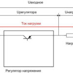
It was mentioned that the LM317 belongs to the class of linear stabilizers. This means that the stabilization of the output voltage is carried out due to the redistribution of energy between the load and the regulating element.
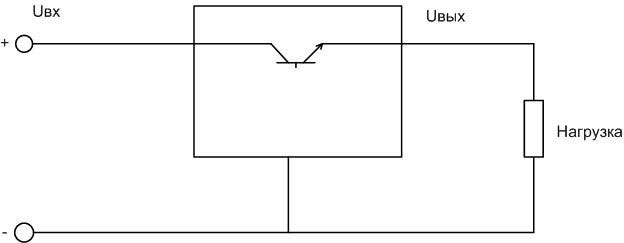
Transistor and load make up input voltage divider. If the voltage set on the load decreases (due to a change in current, etc.), the transistor opens slightly. If it increases, it closes, the division factor changes and the voltage at the load remains stable. The disadvantages of such a scheme are known:
- it is necessary that the input voltage exceed the output;
- a lot of power is dissipated on the regulating transistor;
- Efficiency, even theoretically, cannot exceed the Uout / Uin ratio.
But there are serious advantages (relative to pulse circuits):
- relatively simple and inexpensive chip;
- requires minimal external piping;
- and the main advantage is that the output voltage is free from high-frequency parasitic components (power supply interference is minimal).
Standard scheme for switching on a microcircuit:
- input voltage is applied to the Input pin;
- to output Output - output;
- on Ajust - the reference voltage on which the output depends.
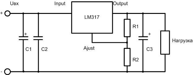
Resistors R1 and R2 set the output voltage. It is calculated by the formula:
Uout=1.25⋅ (1+R2/R1) + Iadj⋅R2.
Iadj is the parasitic current of the tuning pin, according to the manufacturer it can be within 5 µA. Practice shows that it can reach values an order of magnitude or two higher.
Capacitor C1 can have a capacity from hundreds to several thousand microfarads. In most cases, it is the output capacitor of the rectifier. It must be connected to the microcircuit with conductors no longer than 7 cm. If this condition cannot be met for the rectifier capacitor, then an additional capacitance of approximately 100 microfarads should be connected in the immediate vicinity of the input terminal. Capacitor C3 should not have a capacitance of more than 100-200 microfarads for two reasons:
- to avoid the transition of the stabilizer to the self-oscillation mode;
- to eliminate the inrush current to charge when power is applied.
In the second case, overload protection may work.
Do not forget that when current flows through resistors, they heat up (this is also possible when the ambient temperature rises).The resistance R1 and R2 change and there is no guarantee that they will change proportionally. Therefore, the voltage at the output with warming up or cooling down can change. If this is critical, resistors with a normalized temperature coefficient of resistance can be used. They can be distinguished by the presence of six stripes on the body. But such items are more expensive and it is more difficult to buy them. Another option is to use a zener diode for a suitable voltage instead of R2.
What are the analogues
There are similar microcircuits developed in other companies in other countries. Complete analogues are:
- GL317;
- SG317;
- UPC317;
- ECG1900.
Stabilizers with increased electrical characteristics are also produced. More current can be given:
- LM338 - 5 A;
- LM138 - 5 A
- LM350 - 3 A.
If an adjustable voltage source with an upper limit of 60 V is required, stabilizers LM317HV, LM117HV must be used. Index HV means High Voltage - high voltage.
Of the domestic microcircuits, the KR142EN12 is a complete analogue, but it is produced only in the TO-220 package. This must be taken into account when designing printed circuit boards.
Examples of switching circuits for the LM317 stabilizer
Typical schemes for switching on the microcircuit are given in the datasheet. A typical application is a fixed voltage stabilizer, discussed above.
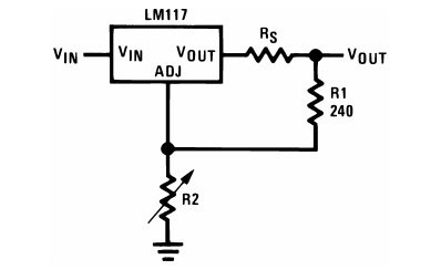
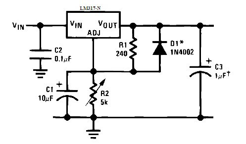
If you install a variable resistor instead of R2, then the output voltage of the regulator can be quickly adjusted. It must be borne in mind that the potentiometer will be a weak point in the circuit. Even with good quality variable resistors, the contact point of the engine with the conductive layer will have some connection instability. In practice, this will result in additional instability of the output voltage.
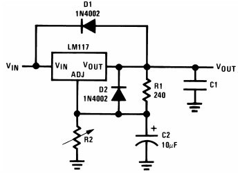
For protection, the manufacturer recommends enabling two diode D1 and D2.The first diode should protect against a situation where the output voltage is higher than the input. In practice, this situation is extremely rare, and can only occur if there are other voltage sources from the output side. The manufacturer notes that this diode also protects against the event of a short circuit at the input - the capacitor C1 in this case will create a discharge current of the opposite polarity, which will lead to failure of the microcircuit. But inside the microcircuit, parallel to this diode, there is a chain of zener diodes and resistors, which will work just the same. Therefore, the need to install this diode is doubtful. And D2 in such a situation will protect the input of the stabilizer from the current of the capacitor C2.
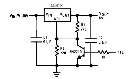
If parallel to R2 put transistor, then the operation of the stabilizer can be controlled. When voltage is applied to the base of the transistor, it opens and shunts R2. The output voltage decreases to 1.25 V. Here it is necessary to ensure that the difference between the input and output voltage does not exceed 40 V.
The detrimental effect of the potentiometer contact on output voltage stability can be reduced by connecting a capacitor in parallel with the variable resistance. In this case, the protective diode D1 will not interfere.
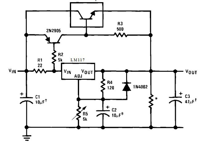
If the output current of the stabilizer is not enough, it can be boosted with an external transistor.
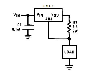
You can get a current stabilizer from a voltage regulator by turning on the LM317 according to this scheme. The output current is calculated by the formula I=1.25⋅R1. Such an inclusion is often used as a driver for LEDs - the LED is turned on as a load.
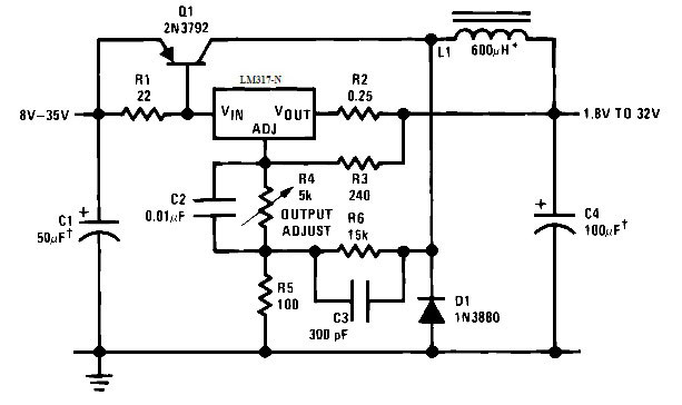
Finally, an unusual inclusion of a linear stabilizer - a circuit was created on its basis switching power supply. Positive feedback for the occurrence of oscillations sets the circuit C3R6.
The LM317 chip has a significant number of weaknesses. But the art of creating circuits is to use the advantages of the stabilizer to bypass the disadvantages. All the minuses of the microcircuit are revealed, advice is given on how to neutralize them. Therefore, the LM317 is popular with the creators of professional and amateur radio equipment.
Similar articles: