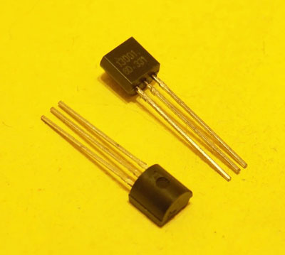
Transistor 13001 (MJE13001) is a silicon triode manufactured using planar epitaxial technology. It has an N-P-N structure. Refers to medium power devices. They are produced mainly in factories located in Southeast Asia and are used in electronic devices manufactured in the same region.
Content
Main technical characteristics
The main features of the 13001 transistor are:
- high operating voltage (base-collector - 700 volts, collector-emitter - 400 volts, according to some sources - up to 480 volts);
- short switching time (current rise time - tr=0.7 microseconds, current decay time tf\u003d 0.6 μs, both parameters are measured at a collector current of 0.1 mA);
- high operating temperature (up to +150 °C);
- high power dissipation (up to 1 W);
- low collector-emitter saturation voltage.
The last parameter is declared in two modes:
| Collector current, mA | Base current, mA | Collector-emitter saturation voltage, V |
|---|---|---|
| 50 | 10 | 0,5 |
| 120 | 40 | 1 |
Also, as an advantage, manufacturers claim a low content in transistor harmful substances (RoHS compliance).
Important! In the datasheets of various manufacturers for transistors of the 13001 series, the characteristics of the semiconductor device vary, so certain inconsistencies are possible (usually within 20%).
Other parameters significant for operation:
- maximum continuous base current - 100 mA;
- the highest pulse base current - 200 mA;
- maximum allowable collector current - 180 mA;
- limiting impulse collector current - 360 mA;
- the highest base-emitter voltage is 9 volts;
- turn-on delay time (storage time) - from 0.9 to 1.8 μs (at a collector current of 0.1 mA);
- base-emitter saturation voltage (at a base current of 100 mA, a collector current of 200 mA) - no more than 1.2 volts;
- the highest operating frequency is 5 MHz.
The static current transfer coefficient for different modes is declared within:
| Collector-emitter voltage, V | Collector current, mA | Gain | |
|---|---|---|---|
| Least | largest | ||
| 5 | 1 | 7 | |
| 5 | 250 | 5 | |
| 20 | 20 | 10 | 40 |
All characteristics are declared at an ambient temperature of +25 °C. The transistor can be stored at ambient temperatures from minus 60 to +150 °C.
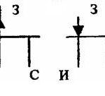
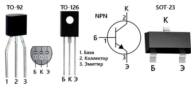
Enclosures and plinth
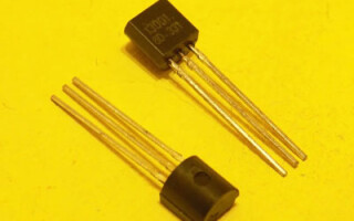
Transistor 13001 is available in output plastic packages with flexible leads for mounting using true hole technology:
- TO-92;
- TO-126.
Also in the line there are cases for surface mounting (SMD):
- SOT-89;
- SOT-23.
Transistors in SMD packages are marked with the letters H01A, H01C.
Important! Transistors from different manufacturers may be prefixed with MJE31001, TS31001 or no prefix.Due to lack of space on the case, the prefix is often not indicated, and such devices may have a different pinout. If there is a transistor of unknown origin, the pinout is best clarified using multimeter or a transistor tester.
Domestic and foreign analogues
Direct analogue transistor 13001 there are no domestic silicon triodes in the nomenclature, but under medium operating conditions, silicon semiconductor devices of the N-P-N structure from the table can be used.
| transistor type | Maximum power dissipation, Watt | Collector-base voltage, volt | Base-emitter voltage, volt | Cut-off frequency, MHz | Maximum collector current, mA | h F.E. |
|---|---|---|---|---|---|---|
| KT538A | 0,8 | 600 | 400 | 4 | 500 | 5 |
| KT506A | 0,7 | 800 | 800 | 17 | 2000 | 30 |
| KT506B | 0,8 | 600 | 600 | 17 | 2000 | 30 |
| KT8270A | 0,7 | 600 | 400 | 4 | 500 | 10 |
At modes close to the maximum, it is necessary to carefully select analogues so that the parameters allow the transistor to be operated in a specific circuit. It is also necessary to clarify the pinout of the devices - it may not coincide with the pinout of 13001, this can lead to problems with installation on the board (especially for the SMD version).
Of foreign analogues, the same high-voltage, but more powerful silicon N-P-N transistors are suitable for replacement:
- (MJE)13002;
- (MJE)13003;
- (MJE)13005;
- (MJE)13007;
- (MJE)13009.
They differ from the 13001 mostly in increased collector current and increased power that the semiconductor device can dissipate, but there may also be differences in package and pinout.
In each case, it is necessary to check the pinout. In many cases, LB120, SI622, etc. transistors may be suitable, but one must carefully compare the specific characteristics.
So, in the LB120, the collector-emitter voltage is the same 400 volts, but more than 6 volts cannot be applied between the base and the emitter. It also has a slightly lower maximum power dissipation - 0.8 W versus 1 W for 13001. This must be taken into account when deciding whether to replace one semiconductor device with another. The same applies to more powerful high-voltage domestic silicon transistors of the N-P-N structure:
| Type of domestic transistor | The highest collector-emitter voltage, V | Maximum collector current, mA | h21e | Frame |
|---|---|---|---|---|
| KT8121A | 400 | 4000 | <60 | CT28 |
| KT8126A | 400 | 8000 | >8 | CT28 |
| KT8137A | 400 | 1500 | 8..40 | CT27 |
| KT8170A | 400 | 1500 | 8..40 | CT27 |
| KT8170A | 400 | 1500 | 8..40 | CT27 |
| KT8259A | 400 | 4000 | up to 60 | TO-220, TO-263 |
| KT8259A | 400 | 8000 | up to 60 | TO-220, TO-263 |
| KT8260A | 400 | 12000 | up to 60 | TO-220, TO-263 |
| KT8270 | 400 | 5000 | <90 | CT27 |
They replace the 13001 series in functionality, have more power (and sometimes higher operating voltage), but the pinout and package dimensions may vary.
Scope of transistors 13001
Transistors of the 13001 series are designed specifically for use in low power converters as key (switching) elements.
- network adapters of mobile devices;
- electronic ballasts for low power fluorescent lamps;
- electronic transformers;
- other impulse devices.
There are no fundamental restrictions on the use of 13001 transistors as transistor switches. It is also possible to use these semiconductor devices in low-frequency amplifiers in cases where special amplification is not required (the current transfer coefficient of the 13001 series is small by modern standards), but in these cases the rather high parameters of these transistors in terms of operating voltage and their high speed are not realized. .
It is better in these cases to use the more common and cheaper types of transistors. Also, when building amplifiers, it must be remembered that the 31001 transistor does not have a complementary pair, so there may be problems with the organization of a push-pull cascade.
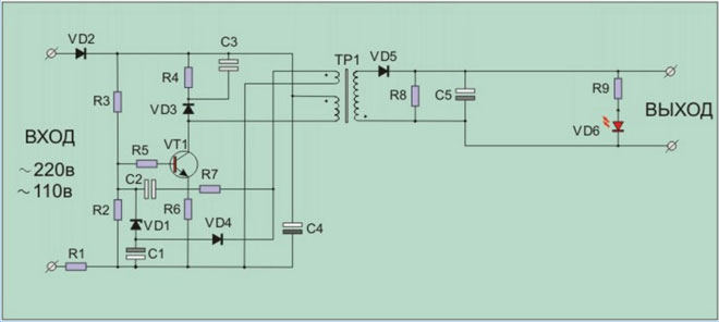
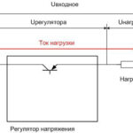
The figure shows a typical example of the use of a transistor 13001 in a mains charger for a portable device battery. A silicon triode is included as a key element that generates pulses on the primary winding of the transformer TP1. It withstands the full rectified mains voltage with a large margin and does not require additional circuitry measures.
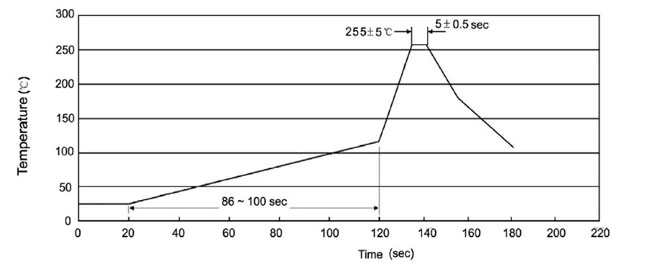
When soldering transistors, some care must be taken to avoid excessive heating. The ideal temperature profile is shown in the figure and consists of three steps:
- the preheating stage lasts about 2 minutes, during which time the transistor warms up from 25 to 125 degrees;
- the actual soldering lasts about 5 seconds at a maximum temperature of 255 degrees;
- the final stage is cooling at a rate of 2 to 10 degrees per second.
This schedule is difficult to follow at home or in the workshop, and it is not so important when dismantling and assembling a single transistor. The main thing is not to exceed the maximum allowable soldering temperature.
The 13001 transistors have a reputation for being reasonably reliable and, under operating conditions within specified limits, can last a long time without failure.
Similar articles: