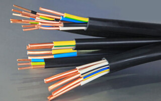
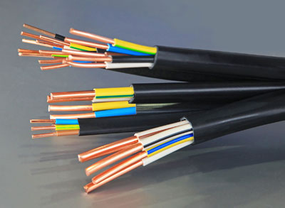
The current in the electrical circuit passes through the conductors from the voltage source to the load, that is, to lamps, appliances. In most cases, copper wires are used as conductors. A circuit can have several elements with different resistances. In the instrument circuit, conductors can be connected in parallel or in series, and there can also be mixed types.
Element scheme with a resistance called a resistor, the voltage of a given element is the potential difference between the ends of the resistor. Parallel and series electrical connection of conductors is characterized by a single principle of operation, according to which the current flows from plus to minus, respectively, the potential decreases. On wiring diagrams, the wiring resistance is taken as 0, since it is negligible.
Parallel connection implies that the elements of the circuit are connected to the source in parallel and are switched on at the same time. Serial connection means that the resistance conductors are connected in strict sequence one after the other.
When calculating, the idealization method is used, which greatly simplifies understanding. In fact, in electrical circuits, the potential gradually decreases in the process of moving through the wiring and elements that are included in a parallel or series connection.
Content
Serial connection of conductors
The serial connection scheme implies that they are switched on in a certain sequence, one after the other. Moreover, the current strength in all of them is equal. These elements create a total voltage on the site. Charges do not accumulate in the nodes of the electrical circuit, because otherwise a change in voltage and current would be observed. With a constant voltage, the current is determined by the value of the resistance of the circuit, therefore, in a series circuit, the resistance changes if one load changes.
The disadvantage of such a scheme is the fact that in the event of failure of one element, the rest also lose the ability to function, since the circuit is broken. An example is a garland that does not work if one bulb burns out. This is a key difference from a parallel connection, where the elements can operate individually.
The series circuit assumes that due to the single-level connection of conductors, their resistance is equal at any point in the network. The total resistance is equal to the sum of the voltage reduction of the individual elements of the network.
With this type of connection, the beginning of one conductor is connected to the end of another. The key feature of the connection is that all conductors are on the same wire without branches, and one electric current flows through each of them. However, the total voltage is equal to the sum of the voltages on each. You can also consider the connection from a different point of view - all conductors are replaced by one equivalent resistor, and the current on it is the same as the total current that passes through all resistors. The equivalent total voltage is the sum of the voltage values across each resistor. This is the potential difference across the resistor.
Using a serial connection is useful when you want to specifically turn on and off a specific device. For example, an electric bell can only ring when there is a connection to a voltage source and a button. The first rule says that if there is no current on at least one of the elements of the circuit, then it will not be on the rest. Accordingly, if there is current in one conductor, it is in the others. Another example would be a battery-powered flashlight, which only shines when there is a battery, a working bulb, and a pressed button.
In some cases, a serial scheme is not practical. In an apartment where the lighting system consists of many lamps, sconces, chandeliers, you should not organize a scheme of this type, since there is no need to turn the lights on and off in all rooms at the same time. For this purpose, it is better to use a parallel connection in order to be able to turn on the light in individual rooms.
Parallel connection of conductors
In a parallel circuit, conductors are a set resistors, some ends of which are assembled into one node, and the other - into the second node. It is assumed that the voltage in the parallel type of connection is the same in all parts of the circuit. Parallel sections of the electrical circuit are called branches and pass between two connecting nodes, they have the same voltage. This voltage is equal to the value on each conductor. The sum of the indicators, the reciprocal of the resistance of the branches, is also inverse with respect to the resistance of a separate section of the parallel circuit circuit.
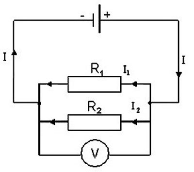
With parallel and series connections, the system for calculating the resistances of individual conductors is different. In the case of a parallel circuit, the current flows through the branches, which increases the conductivity of the circuit and reduces the total resistance. When several resistors with similar values are connected in parallel, the total resistance of such an electrical circuit will be less than one resistor a number of times equal to the number of resistors in the circuit.
Each branch has one resistor, and the electric current, when it reaches the branching point, is divided and diverges to each resistor, its final value is equal to the sum of the currents on all resistances. All resistors are replaced with one equivalent resistor. Applying Ohm's law, the value of the resistance becomes clear - in a parallel circuit, the values reciprocal of the resistances on the resistors are summed up.
With this circuit, the current value is inversely proportional to the resistance value. The currents in the resistors are not interconnected, so if one of them is turned off, this will in no way affect the others. For this reason, such a scheme is used in many devices.
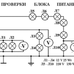
Considering the possibilities of using a parallel circuit in everyday life, it is advisable to note the lighting system of the apartment. All lamps and chandeliers must be connected in parallel, in which case turning one of them on and off does not affect the operation of the other lamps. Thus adding switch each light bulb in the circuit branch, you can turn on and off the corresponding lamp as needed. All other lamps work independently.
All electrical appliances are connected in parallel to a 220 V power grid, then they are connected to a switchboard. That is, all devices are connected regardless of the connection of other devices.
Laws of series and parallel connection of conductors
For a detailed understanding in practice of both types of compounds, we present formulas that explain the laws of these types of compounds. The power calculation for parallel and series connection type is different.
In a series circuit, there is the same current strength in all conductors:
I = I1 = I2.
According to Ohm's law, these types of conductor connections are explained differently in different cases. So, in the case of a series circuit, the voltages are equal to each other:
U1 = IR1, U2 = IR2.
In addition, the total voltage is equal to the sum of the voltages of individual conductors:
U = U1 + U2 = I(R1 + R2) = IR.
The total resistance of the electrical circuit is calculated as the sum of the active resistances of all conductors, regardless of their number.
In the case of a parallel circuit, the total voltage of the circuit is similar to the voltage of the individual elements:
U1 = U2 = U.
And the total strength of the electric current is calculated as the sum of the currents that are available in all conductors located in parallel:
I = I1 + I2.
To ensure the maximum efficiency of electrical networks, it is necessary to understand the essence of both types of connections and apply them appropriately, using the laws and calculating the rationality of practical implementation.
Mixed connection of conductors
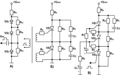
Series and parallel resistance connections can be combined in one electrical circuit if necessary. For example, it is allowed to connect parallel resistors in series to another resistor or their group, this type is considered combined or mixed.
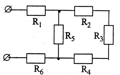
In such a case, the total resistance is calculated by taking the sum of the values for the parallel connection in the system and for the series connection. First you need to calculate the equivalent resistance of the resistors in series, and then the elements of the parallel. A serial connection is considered a priority, and circuits of this combined type are often used in household appliances and appliances.
So, considering the types of connections of conductors in electrical circuits and based on the laws of their functioning, one can fully understand the essence of the organization of circuits of most household electrical appliances. With parallel and series connections, the calculation of resistance and current strength indicators is different. Knowing the principles of calculation and formulas, you can competently use each type of circuit organization to connect elements in the best way and with maximum efficiency.
Similar articles: