When developing electronic circuits, it is usually necessary to solve the problem of amplifying signals - increasing their amplitude or power. But there are situations when the signal level is required, on the contrary, to weaken. And this task is not as simple as it seems at first glance.
Content
What is an attenuator and how does it work
An attenuator is a device for intentionally and normally reducing the amplitude or power of an input signal without distorting its shape.
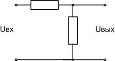
The principle of operation of attenuators used in the radio frequency range - voltage divider with resistors or capacitors. The input signal is distributed between the resistors in proportion to the resistances. The simplest solution is a divider of two resistors. Such an attenuator is called L-shaped (in foreign technical literature - L-shaped). Either side of this unbalanced device can serve as input and output.A feature of the G-attenuator is a low level of losses when matching the input and output.
Types of attenuators
In practice, the G-attenuator is not used so often - mainly to match the input and output resistances. P-type devices (in foreign literature Pi - from the Latin letter π) and T-type devices are used much more widely for normalized attenuation of signals. This principle allows you to create devices with the same input and output impedance (but, if necessary, you can use different ones).
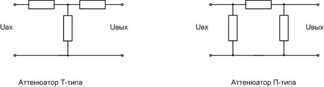
The figure shows unbalanced devices. The source and load must be connected to them with unbalanced lines - coaxial cables, etc. from any direction.
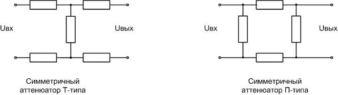
For balanced lines (twisted pair, etc.), balanced circuits are used - they are sometimes called H- and O-type attenuators, although these are just variations of the previous devices.
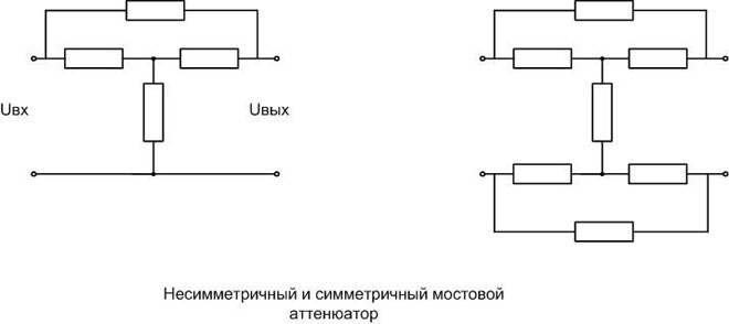
By adding one (two) resistors, the attenuator T- (H-) types are converted into bridge ones.
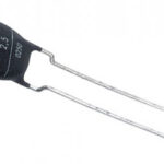
Attenuators are produced by the industry in the form of complete devices with connectors for connection, but they can also be made on a printed circuit board as part of a general circuit. Resistive and capacitive attenuators have a serious plus - they do not contain non-linear elements, which does not distort the signal and does not lead to the appearance of new harmonics in the spectrum and the disappearance of existing ones.
In addition to resistive, there are other types of attenuators. Widely used in industrial technology:
- limit and polarization attenuators - based on the design properties of waveguides;
- absorbing attenuators - signal attenuation causes power absorption by specially selected materials;
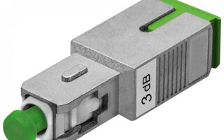
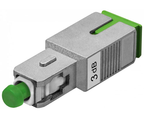
- optical attenuators;
These types of devices are used in microwave technology and in the light frequency range. At low and radio frequencies, attenuators based on resistors and capacitors are used.
Main characteristics
The main parameter that determines the properties of attenuators is the attenuation coefficient. It is measured in decibels. To understand how many times the signal amplitude decreases after passing through the attenuating circuit, it is necessary to recalculate the coefficient from decibels to times. At the output of a device that reduces the signal amplitude by N decibels, the voltage will be M times less:
M=10(N/20) (for power — M=10(N/10)) .
Reverse calculation:
N=20⋅log10(M) (for power N=10⋅log10(M)).
So, for an attenuator with Kosl \u003d -3 dB (the coefficient is always negative, since the value always decreases), the output signal will have an amplitude of 0.708 from the original. And if the output amplitude is two times less than the original one, then Kosl is approximately equal to -6 dB.
The formulas are quite complex for mental calculations, so it is better to use online calculators, of which there are a great many on the Internet.
For adjustable devices (stepped or smooth), adjustment limits are indicated.
Another important parameter is the impedance (impedance) at the input and output (they can be the same). This resistance is associated with such a characteristic as the standing wave ratio (SWR) - it is often indicated on industrial products. For a purely resistive load, this coefficient is calculated by the formula:
- SWR=ρ/R if ρ>R, where R is the load resistance and ρ is the wave impedance of the line.
- SWR= R/ρ if ρ<R.
SWR is always greater than or equal to 1. If R=ρ, all power is transferred to the load. The more these values differ, the greater the loss.So, with SWR = 1.2, 99% of the power will reach the load, and with SWR = 3 - already 75%. When connecting a 75 ohm attenuator to a 50 ohm cable (or vice versa), SWR = 1.5 and the loss will be 4%.
Other important features to mention:
- operating frequency range;
- maximum power.
Also important is such a parameter as accuracy - it means the allowable deviation of the attenuation from the nominal. For industrial attenuators, the characteristics are applied to the case.
In some cases, the power of the device is important. The energy that has not reached the consumer is dissipated by the attenuator elements, so it is critical to prevent overload.
There are formulas for calculating the main characteristics of resistive attenuators of various designs, but they are cumbersome and contain logarithms. Therefore, to use them, you need at least a calculator. Therefore, for self-calculation it is more convenient to use special programs (including online).
Adjustable attenuators
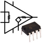
The attenuation coefficient and SWR are affected by the value of all the elements that make up the attenuator, so create devices based on resistors with smooth regulation of parameters is difficult. By changing the attenuation, it is necessary to adjust the SWR and vice versa. Such problems can be solved by using amplifiers with a gain less than 1.
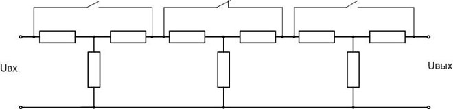
Such devices are built on transistors or OU, but there is a problem of linearity. It is not easy to create an amplifier that does not distort the waveform over a wide frequency range. Stepwise regulation is much more widely used - the attenuators are connected in series, their weakening is added up. Those circuits that are needed are shunted (relay contacts etc).So the desired attenuation coefficient is gained without changing the wave resistance.
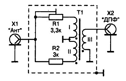
There are designs of devices for attenuating the signal with smooth adjustment, built on broadband transformers (SHPT). They are used in amateur communication technology in cases where the requirements for matching the input and output are low.
Smooth tuning of attenuators built on waveguides is achieved by changing the geometric dimensions. Optical attenuators are also produced with smooth attenuation control, but such devices have a rather complicated design, since they contain a system of lenses, optical filters, etc.
Application area
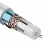
If the attenuator has different input and output resistances, then, in addition to the attenuation function, it can act as a matching device. So, if you need to connect cables of 75 and 50 ohms, you can put an appropriately calculated one between them, and together with the normalized attenuation, you can also correct the degree of matching.
In receiving equipment, attenuators are used to avoid overloading the input circuits with powerful spurious radiation. In some cases, attenuating the interfering signal, even at the same time as a weak wanted signal, can improve reception quality by reducing the level of intermodulation interference.
In measurement technology, attenuators can be used as decoupling - they reduce the effect of the load on the source of the reference signal. Optical attenuators are widely used in testing transceiver equipment for fiber optic communication lines.With their help, attenuation in a real line is modeled and the conditions and boundaries of stable communication are determined.
In audio technology, attenuators are used as power control devices. Unlike potentiometers, they do this with less power loss. Here it is easier to ensure smooth adjustment, since the wave resistance is not important - only attenuation matters. In television cable networks, attenuators prevent overloading of TV inputs and allow you to maintain transmission quality regardless of reception conditions.
Being not the most complex device, the attenuator finds the widest application in radio frequency circuits and allows you to solve various problems. At microwave and optical frequencies, these devices are built differently, and they are complex industrial units.
Similar articles: