A trigger is an element of digital technology, a bistable device that switches to one of the states and can stay in it indefinitely even when external signals are removed. It is built from logical elements of the first level (AND-NOT, OR-NOT, etc.) and belongs to the logical devices of the second level.
In practice, flip-flops are produced in the form of microcircuits in a separate package or are included as elements in large integrated circuits (LSI) or programmable logic arrays (PLM).
Content
Classification and types of trigger synchronization
Triggers fall into two broad classes:
- asynchronous;
- synchronous (clocked).
The fundamental difference between them is that for the first category of devices, the output signal level changes simultaneously with the change in the signal at the input (inputs).For synchronous triggers, a state change occurs only if there is a synchronizing (clock, strobe) signal at the input provided for this. For this, a special output is provided, denoted by the letter C (clock). According to the type of gating, synchronous elements are divided into two classes:
- dynamic;
- static.
For the first type, the output level changes depending on the configuration of the input signals at the time of the appearance of the front (leading edge) or the fall of the clock pulse (depending on the specific type of trigger). Between the appearance of synchronizing fronts (slopes), any signals can be applied to the inputs, the state of the trigger will not change. In the second option, the sign of clocking is not a change in level, but the presence of one or zero at the Clock input. There are also complex trigger devices classified by:
- the number of stable states (3 or more, in contrast to 2 for the main elements);
- the number of levels (also more than 3);
- other characteristics.
Complex elements are of limited use in specific devices.
Types of triggers and how they work
There are several basic types of triggers. Before understanding the differences, a common property should be noted: when power is applied, the output of any device is set to an arbitrary state. If this is critical to the overall operation of the circuit, presetting circuits must be provided. In the simplest case, this is an RC circuit that generates a signal for setting the initial state.
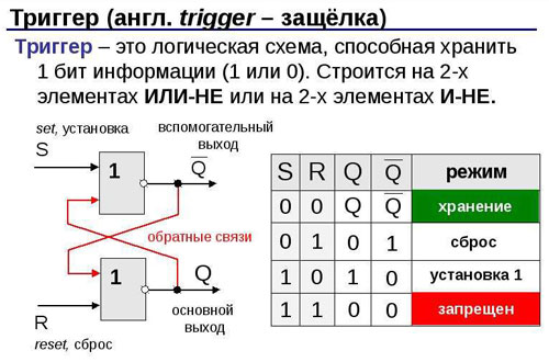
RS flip-flops
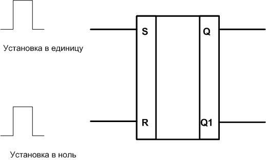
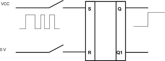
The most common type of asynchronous bistable device is the RS flip-flop. It refers to flip-flops with separate setting of state 0 and 1.There are two inputs for this:
- S - set (installation);
- R - reset (reset).
There is a direct output Q, there can also be an inverted output Q1. The logic level on it is always the opposite of the level on Q - this is useful when designing circuits.
When a positive level is applied to the input S, the output Q will be set to a logical unit (if there is an inverted output, it will go to level 0). After that, at the input of the setup, the signal can change as you like - this will not affect the output level. Until one appears at the input R. This will set the flip-flop to state 0 (1 on the inverted output). Now changing the signal at the reset input will not affect the further state of the element.
Important! The option when there is a logical unit at both inputs is forbidden. The trigger will be set to an arbitrary state. When designing schemes, this situation should be avoided.
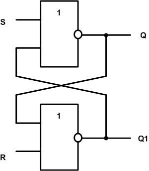
An RS flip-flop can be built on the basis of widely used two-input NAND elements. This method is implemented both on conventional microcircuits and inside programmable matrices.
One or both inputs can be inverted. This means that on these pins, the trigger is controlled by the appearance of not a high, but a low level.
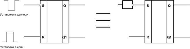
If you build an RS flip-flop on two-input AND-NOT elements, then both inputs will be inverse - controlled by the supply of a logical zero.
There is a gated version of the RS flip-flop. It has an additional input C. Switching occurs when two conditions are met:
- the presence of a high level at the Set or Reset input;
- the presence of a clock signal.
Such an element is used in cases where the switching must be delayed, for example, at the time of the end of transients.
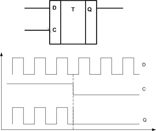
D flip-flops
D-trigger ("transparent trigger", "latch", latch) belongs to the category of synchronous devices, clocked by input C. There is also a data input D (Data). In terms of functionality, the device belongs to triggers with the receipt of information through one input.
As long as a logical one is present at the clock input, the signal at the output Q repeats the signal at the data input (transparency mode). As soon as the strobe level goes to state 0, the level at the output Q will remain the same as it was at the time of the edge (latches). So you can fix the input level at the input at any time. There are also D-flip-flops with clocking on the front. They latch the signal on the positive edge of the strobe.
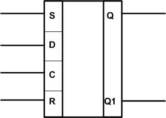
In practice, two types of bistable devices can be combined in one microcircuit. For example, D and RS flip-flop. In this case, the Set/Reset inputs have priority. If there is a logical zero on them, then the element behaves like a normal D-flip-flop. When a high level occurs at least one input, the output is set to 0 or 1, regardless of the signals at inputs C and D.
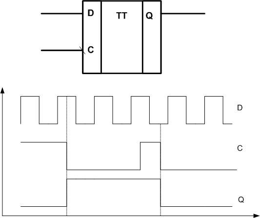
The transparency of a D flip-flop is not always a useful feature. To avoid it, double elements are used (flip-flop, “clapping” trigger), they are denoted by the letters TT. The first trigger is a regular latch that passes the input signal to the output. The second trigger serves as a memory element. Both devices are clocked with one strobe.
T-flip-flops
The T-trigger belongs to the class of countable bistable elements. The logic of its work is simple - it changes its state every time when the next logical unit comes to its input.If a pulse signal is applied to the input, the output frequency will be twice as high as the input. At the inverted output, the signal will be out of phase with the direct one.
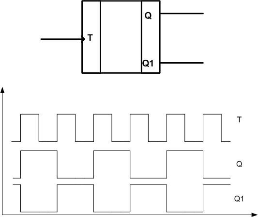
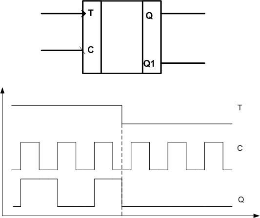
This is how an asynchronous T-flip-flop works. There is also a synchronous option. When a pulse signal is applied to the clock input and in the presence of a logical unit at the output T, the element behaves in the same way as an asynchronous one - it divides the input frequency in half. If the T pin is logic zero, then the Q output is set low, regardless of the presence of strobes.
 JK flip-flops
This bistable element belongs to the category of universal ones. It can be controlled separately by inputs. The logic of the JK flip-flop is similar to the work of the RS element. The J (Job) input is used to set the output to one. A high level on the K (Keep) pin resets the output to zero. The fundamental difference from the RS-trigger is that the simultaneous appearance of ones on two control inputs is not forbidden. In this case, the output of the element changes its state to the opposite.
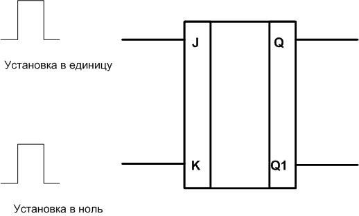
If the Job and Keep outputs are connected, then the JK-flip-flop turns into an asynchronous counting T-flip-flop. When a square wave is applied to the combined input, the output will be half the frequency. Like the RS element, there is a clocked version of the JK flip-flop. In practice, it is mainly gated elements of this type that are used.
Practical use
The property of triggers to retain the recorded information even when external signals are removed allows them to be used as memory cells with a capacity of 1 bit.From single elements, you can build a matrix for storing binary states - according to this principle, static random access memories (SRAM) are built. A feature of such memory is a simple circuitry that does not require additional controllers. Therefore, such SRAMs are used in controllers and PLAs. But the low recording density prevents the use of such matrices in PCs and other powerful computing systems.
The use of flip-flops as frequency dividers was mentioned above. Bistable elements can be connected in chains and get different division ratios. The same string can be used as a pulse counter. To do this, it is necessary to read the state of the outputs from the intermediate elements at each moment of time - a binary code will be obtained corresponding to the number of pulses that came to the input of the first element.
Depending on the type of triggers applied, counters can be synchronous or asynchronous. Serial-to-parallel converters are built on the same principle, but only gated elements are used here. Also, digital delay lines and other elements of binary technology are built on triggers.
RS flip-flops are used as level clamps (bounce suppressors). If mechanical switches (buttons, switches) are used as logic level sources, then when pressed, the bounce effect will form many signals instead of one. The RS flip-flop successfully fights this.
The scope of bistable devices is wide. The range of tasks solved with their help largely depends on the imagination of the designer, especially in the field of non-standard solutions.
Similar articles: