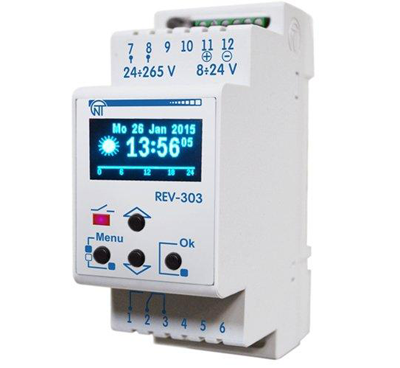
In modern equipment, a timer is often needed, i.e. a device that does not work immediately, but after a period of time, so it is also called a delay relay. The device creates time delays for turning other devices on or off. It is not necessary to purchase it in a store, because a well-designed home-made time relay will effectively perform its functions.
Content
Scope of time relay application
Areas of use of the timer:
- regulators;
- sensors;
- automation;
- various mechanisms.
All these devices are divided into 2 classes:
- Cyclic.
- Intermediate.
The first is considered an independent device. It gives a signal after a specified time period. In automatic systems, a cyclic device turns on and off the necessary mechanisms. With its help, lighting is controlled:
- on the street;
- in aquarium;
- in a greenhouse.
The cyclic timer is an integral device in the Smart Home system. It is used to perform the following tasks:
- Turning the heating on and off.
- Event reminder.
- At a strictly specified time, it turns on the necessary devices: a washing machine, a kettle, a light, etc.
In addition to the above, there are other industries in which a cyclic delay relay is used:
- the science;
- the medicine;
- robotics.
Intermediate relay is used for discrete circuits and serves as an auxiliary device. It performs automatic interruption of the electrical circuit. The scope of the intermediate timer of the time relay begins where signal amplification and galvanic isolation of the electrical circuit are necessary. Intermediate timers are divided into types depending on the design:
- Pneumatic. The relay operation after the signal is received does not occur instantly, the maximum operation time is up to one minute. It is used in control circuits of machine tools. The timer controls the actuators for step control.
- Motor. The time delay setting range starts from a couple of seconds and ends with tens of hours. Delay relays are part of overhead power line protection circuits.
- Electromagnetic. Designed for DC circuits. With their help, acceleration and deceleration of the electric drive occur.
- With clockwork. The main element is a cocked spring. Regulation time - from 0.1 to 20 seconds. Used in relay protection of overhead power lines.
- Electronic. The principle of operation is based on physical processes (periodic pulses, charge, capacity discharge).
Schemes of various time relays
There are different versions of the time relay, each type of circuit has its own characteristics. Timers can be made independently.Before you make a time relay with your own hands, you need to study its device. Schemes of simple time relays:
- on transistors;
- on microchips;
- for 220 V output power.
Let's describe each of them in more detail.
Transistor circuit
Required radio parts:
- Transistor KT 3102 (or KT 315) - 2 pcs.
- Capacitor.
- Resistor with a nominal value of 100 kOhm (R1). You will also need 2 more resistors (R2 and R3), the resistance of which will be selected along with the capacitance, depending on the timer operation time.
- Button.
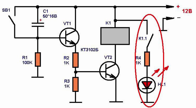
When the circuit is connected to a power source, the capacitor will begin to charge through resistors R2 and R3 and the emitter of the transistor. The latter will open, so the voltage will drop across the resistance. As a result, the second transistor will open, which will lead to the operation of the electromagnetic relay.
When the capacitance is charged, the current will decrease. This will cause a decrease in the emitter current and a voltage drop across the resistance to a level that will lead to the closing of the transistors and the release of the relay. To start the timer again, a short press of the button will be required, which will cause the capacity to completely discharge.
To increase the time delay, an insulated gate field effect transistor circuit is used.
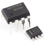
Chip-based
The use of microcircuits will remove the need to discharge the capacitor and select the ratings of radio components to set the required response time.
Necessary electronic components for a 12 volt time relay:
- resistors with a nominal value of 100 Ohm, 100 kOhm, 510 kOhm;
- diode 1N4148;
- capacitance at 4700 uF and 16 V;
- button;
- chip TL 431.
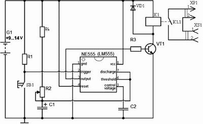
The positive pole of the power supply must be connected to the button, to which one relay contact is connected in parallel.The latter is also connected to a 100 ohm resistor. On the other hand, the resistor is connected with resistances of 510 and 100 kOhm. One of the conclusions of the latter goes to the microcircuit. The second output of the microcircuit is connected to a 510 kΩ resistor, and the third output is connected to a diode. The second contact of the relay is connected to the semiconductor device, which is connected to the executing device. The negative pole of the power supply is connected to a 510 kΩ resistor.
Powered at the output 220 V
The two circuits described above are designed for a voltage of 12 V, i.e., they are not suitable for powerful loads. It is permissible to eliminate this drawback with the help of a magnetic starter installed at the output.
If a low-power device acts as a load (domestic lighting, a fan, a tubular electric heater), then a magnetic starter can be dispensed with. The role of the voltage converter will be performed by a diode bridge and a thyristor. Required details:
- Diodes designed for current more than 1 A and reverse voltage not higher than 400 V - 4 pcs.
- Thyristor VT 151 — 1 pc.
- Capacitance at 470 nF - 1 pc.
- Resistors: 4300 kΩ - 1 pc, 200 ohm - 1 pc., Adjustable 1500 ohm - 1 pc.
- Switch.
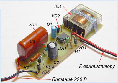
The contact of the diode bridge and the switch are connected to the 220 V supply. The second contact of the bridge is connected to the switch. A thyristor is connected in parallel to the diode bridge. The thyristor is connected to a diode and resistances of 200, 1500 ohms. The second terminals of the diode and resistor (200 ohms) go to the capacitor. Parallel to the latter, a 4300 kΩ resistance is connected. But it must be remembered that this device is not used for powerful loads.
Similar articles: