When designing electronic circuits, it is often necessary to compare the level of two voltages. For this, a device such as a comparator is used. The name of the node goes back to the Latin comparare, or, rather, to the English to compare - to compare.
Content
What is a voltage comparator
In the general case, a comparator is a device that has two inputs for supplying the compared values (voltages) and an output for the result of the comparison. The comparator has two inputs for supplying the compared parameters - direct and inverse. The output is set to a logical unit when the voltage of the direct input exceeds the inverse one, and zero - if vice versa. If, with a positive difference between the inverse and direct input, one is set, and in the opposite situation - zero, then such a comparator is called inverting.
The principle of operation of the comparator
It is convenient to build a comparator on operational amplifier (OU).For this, its properties are directly used:
- amplification of the signal difference between the direct and inverting input;
- infinite (in practice - from 10000 and above) amplification factor.
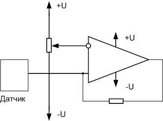
The operation of the op amp as a comparator can be considered with the following switching scheme:
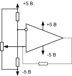
Let there be an op-amp with a gain of 10000, the supply voltage is bipolar, + 5 V and minus 5 V. divider at the inverting input, the reference level is set to exactly 0 volts, at the direct input, minus 5 volts is removed from the potentiometer slider. The operational amplifier should amplify the difference by 10,000 times, theoretically, a voltage of minus 50,000 volts should appear at the output. But the opamp has nowhere to take such a voltage, and it creates the maximum possible - the supply voltage, minus 5 volts.
If you start raising the voltage at the direct input, the op amp will try to set the voltage difference between the inputs, multiplied by 10000. It will succeed when the input voltage approaches zero and becomes approximately minus 0.0005 V. With a further increase in the input voltage at the positive input, the output will rise to zero and above, and at a voltage of +0.0005 volts it will become +5 V and will not rise further - there is nowhere. Thus, when the input voltage passes the zero level (more precisely, minus 0.0005 volts - + 0.0005), the output voltage will jump from minus 5 volts to +5 volts. In other words, as long as the voltage at the direct input is lower than at the inverting input, the comparator output is set to zero. If higher - one.
Of interest is the section of the level difference at the inputs from minus 0.0005 volts to + 0.0005.In theory, when it passes, a smooth rise from negative to positive supply voltage will occur. In practice, this range is very narrow, and due to interference, interference, supply voltage instability, etc. with an approximate equality of voltages at the inputs, a chaotic operation of the comparator in both directions will occur. The lower the gain of the op-amp, the wider this window of instability. If the comparator controls the actuator, then this will cause it to work in time (clicking the relay, slamming the valve, etc.), which can lead to its mechanical failure or overheating.
To avoid this, a shallow positive feedback is created by turning on the resistor indicated by the dashed line. This creates a slight hysteresis, shifting the switching thresholds as the voltage passes up and down relative to the reference. For example, the comparator will switch up at 0.1 volts, and down at exactly zero (depending on the depth of feedback). This will eliminate the instability window. The value of this resistor can be from several hundred kilo-ohms to several mega-ohms. The lower the resistance, the greater the difference between the thresholds.
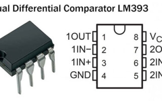
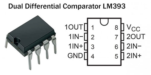
There are also specialized comparator ICs. For example, LM393. In such microcircuits, there is a high-speed operational amplifier (or several), a built-in divider can be installed that creates a reference voltage. Another difference between such comparators and devices built on general purpose op amps is that many of them require a unipolar power supply. Most opamps require bipolar voltage. The choice of the type of microcircuit is made during the development of the device.
Features of digital comparators
Comparators are also used in digital technology, although this sounds, at first glance, paradoxical. After all, there are only two voltage levels - one and zero. And it's pointless to compare them. But you can compare two binary numbers, which can be converted to any analog values (including voltage).
Let there be two binary words of the same length in bits:
X=X3X2X1X0 and Y=Y3Y2Y1Y.
They are considered equal in value if all bits are bitwise equal:
1101=1101 => X=Y.
If at least one bit is different, then the numbers are not equal. The larger number is determined by a bitwise comparison, starting with the most significant bit:
- 1101>101 - here the first bit of X is greater than the first bit of Y, and X>Y;
- 1101>101 - the first bits are equal, but the second bit of X is greater and X>Y;
- 111<1110 - Y has a larger third bit, and the larger value of the least significant digit of X does not matter, X<Y.
The implementation of such a comparison can be built on the logic circuits of the basic elements AND-NOT, OR-NOT, but it is easier to use finished products. For example, 4063 (CMOS), 7485 (TTL), domestic K564IP2 and other series of microcircuits. They are 2-8 bit comparators with a corresponding number of data and control inputs. In most cases, digital comparators have 3 outputs:
- more;
- less;
- equals.
Unlike analog devices, with binary comparators, equality at the inputs is not an undesirable situation and is not tried to be avoided.
Such a device is also easy to build programmatically using Boolean algebra functions.Another option - many microcontrollers have "on board" analog comparators with separate external outputs, which output a ready-made result of comparing two values \u200b\u200bin the form of 0 or 1 to the internal circuit. This saves the resource of small computing systems.
Where is the voltage comparator used?
The scope of the comparator is wide. On it, for example, you can build a threshold relay. To do this, you need a sensor that converts any value into voltage. This value can be:
- illumination level;
- noise level;
- liquid level in a vessel or tank;
- any other values.
The potentiometer can be used to set the trigger level of the comparator. The output signal through the key is given to the indicator or actuator.
If you increase the hysteresis, then the comparator can work as a Schmitt trigger. When a slowly changing voltage is applied to the input, the output will be discrete signal with steep fronts.
The two elements can be connected to form a two-threshold comparator, or a window comparator.
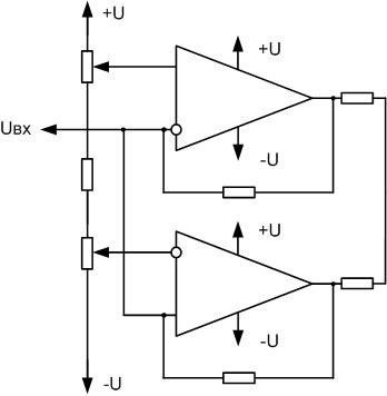
Here, the threshold voltage is set separately for each comparator - for the upper one at the direct input, for the lower one at the inverse one. Free inputs are combined, they are supplied with the measured voltage. The outputs are connected according to the "mounting OR" scheme. When the voltage goes beyond the set upper or lower limit, one of the comparators outputs a high level at the output.
A multilevel comparator is assembled from several elements, which can be used as a linear voltage indicator, or a value that is converted to voltage. For four levels, the scheme will be as follows:
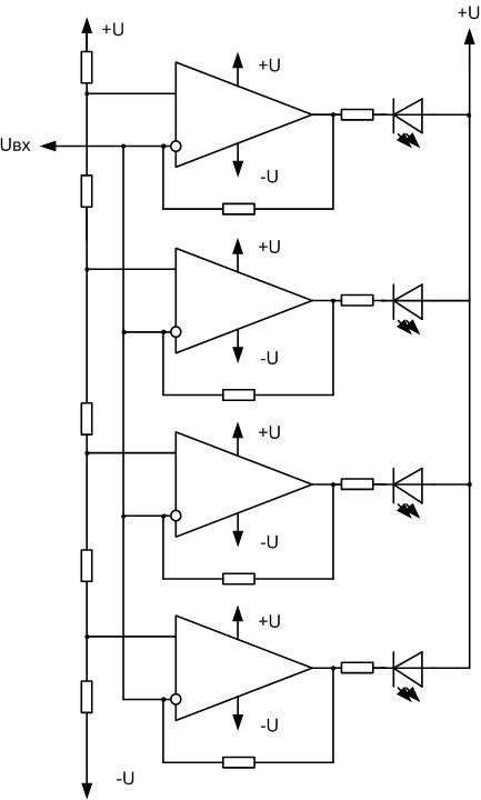
In this circuit, a reference voltage is applied to the input of each element. The inverting inputs are connected together, they receive the measured signal. When the trigger level is reached, the corresponding LED lights up. If the radiating elements are arranged in a line, a light strip will be obtained, the length of which varies in accordance with the level of the applied voltage.
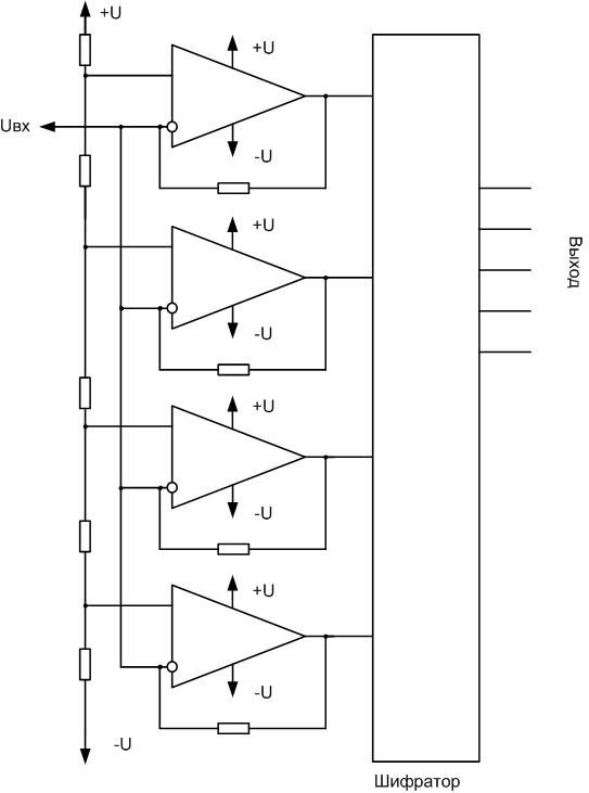
The same circuit can be used as an analog-to-digital converter (ADC). It converts the input voltage into the corresponding binary code. The more elements are included in the ADC, the greater the bit depth, the more accurate the conversion. In practice, the line code is inconvenient to use, and it is converted into a familiar code using an encoder. The encoder can be built on logical elements, use a ready-made microcircuit, or use a ROM with the appropriate firmware.
The scope of comparators in professional and amateur circuitry is diverse. Proper use of these elements allows solving a wide range of problems.
Similar articles: