Sensors - converters of one physical quantity to another (usually, to electrical) are widely used in household and industrial equipment. Without them, it is very difficult, if not impossible, to measure, digitize and process such technological parameters as pressure and flow (gas or liquid), temperature, level, magnetic or electric field strength, etc. One of the most widely used sensors is the Hall sensor - they are used both in everyday life (starting with smartphones or laptops), and in the most complex industrial technology.
Content
 Hall effect - principle of operation
This effect was discovered in 1879 by the American physicist Edwin Hall and named after him.The essence of the phenomenon is that if you take a metal plate and pass an electric current through it (in the direction AB in the figure), and then act on the plate with a magnetic field, for example, created by a permanent magnet, then in the direction perpendicular to the passage of current (CD in the figure ), there will be a potential difference.
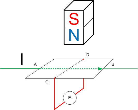
This effect occurs due to the Lorentz force acting on moving charges and displacing them in a direction perpendicular to the direction of motion. As a result, a potential difference arises at the edges of the plate, which can be measured or used to trigger actuators (pre-amplifying). This difference depends on:
- from the strength of the flowing current;
- from the strength of the magnetic field;
- on the concentration of free charge carriers in the conductor.
The phenomenon is named after its discoverer - the Hall effect.
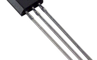
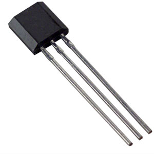
Types and arrangement of Hall sensors
The effect, discovered back in the century before last, found practical application. Based on it, magnetic field sensors are built. Their advantage is that they do not have moving and rubbing elements (unlike reed switches), so their reliability is much higher. According to the principle of sensitivity industrial sensors Halls are divided into:
- unipolar (react only to one magnetic pole - north or south);
- bipolar (turn on when exposed to a magnetic field of one polarity, turn off when exposed to a magnetic field of opposite polarity);
- omnipolar - react to any poles of magnets.
The potential difference created by the action of a magnetic field on moving charges is units, at best tens of microvolts. For practical application, this is not enough, the potential difference must be increased. These amplifiers are built directly into the body of the sensors, and according to the type of amplifier, the devices are divided into two classes.
- Analog. In them, the voltage at the output of the sensor is proportional to the magnetic field (it depends on the strength of the magnet and the distance from it). Built on the basis of an operational amplifier and are used to measure magnetic fields.
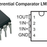
- Digital. After amplifier installed comparator or Schmitt trigger. The output voltage, when the magnetic induction reaches a certain threshold, jumps from zero to a high level (usually to the supply voltage level). Such sensors are used to build magnetic relays or pulse generators. The amplified signal from the plate is applied to the threshold device. When the set level is reached, the sensor is triggered. The trigger level can be adjusted by changing the distance from the sensor to the source of the magnetic field.
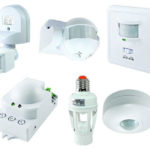
Application of Hall sensors
The most common application of the Hall sensor in everyday life is non-contact car ignition systems. Their advantage is the absence of mechanical contact groups. This means no wear, no burning of contacts, no risk of mechanical failure.
The distribution system includes a plate with ledges driven by the engine crankshaft, a permanent magnet and the Hall sensor itself. When the plate rotates, the protrusions at a strictly defined moment, determined by the position of the crankshaft, fall into the gap between the sensor and the magnet, changing the parameters of the magnetic field.The sensor generates pulses synchronized with the rotation of the crankshaft, which regulate the voltage supply to the high-voltage coil at the required time points. Also, magnetic field sensors in the car are used to recognize the position of the crankshaft.
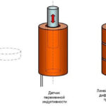
Another use of magnetically sensitive sensors is to determine the position of the rotors of electric motors. The relay element is mounted on the motor stator and is activated when the pole passes. On this principle, you can build a rev counter or a speed meter.
Devices built on the Hall effect are used in laptops or mobile devices - as an indicator of the closed position of the lid. When the sensor is triggered, the computer goes to sleep or shuts down. And in smartphones, one of the functions of the sensor that responds to the Earth's magnetic field is the organization of the electronic compass.
Analog Hall sensors are used in measuring instruments - where it is necessary to assess the level of the magnetic field. They are indispensable for non-contact measurement of current strength in a conductor. As you know, when current passes through a conductor, a magnetic field arises around it. Its intensity depends on the strength of the current. If the current is alternating, then the field can be measured in other ways (for example, with a current transformer), but with direct current, a Hall sensor is indispensable. DC current clamps work on this principle.
The most exotic application of the Hall effect is the construction of ion rocket engines on its principle.
How to check the Hall sensor for performance
To check the sensor, you can assemble a simple circuit, for which, in addition to the sensor itself, you will need:
- power supply for the desired voltage;
- resistor with a resistance of about 1 kOhm;
- Light-emitting diode;
- magnet.
If there is no LED, then instead of it (and the current-limiting resistor) you can use a multimeter (digital or pointer) in voltage measurement mode.
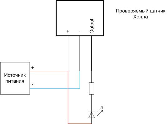
There are no special requirements for the power supply - the currents in the circuit are very small. Its voltage must be within the supply voltage of the sensor under test. The LED is connected with the anode to the plus of the voltage source, the cathode to the output of the device under test, since the sensor is usually made with an open collector (but it is better to check it on the datasheet).
The test procedure depends on the type of device under test.
- To test a unipolar digital sensor, you need to bring a magnet to it with one pole. The LED should light up (the arrow of the pointer voltmeter deviates or the readings of the digital tester change abruptly). When the magnet is removed a considerable distance, the circuit should return to its original position. If the sensor does not work, it is necessary to turn the magnet over with the other pole and repeat the procedure. If the LED flashes, then the sensor is working. If success was not achieved in any position of the magnet, the device is unusable.
- A bipolar digital sensor is tested using a similar technique, only the LED lights up at one position of the magnet, and does not go out when the magnetic field source is removed. The circuit should not react to further manipulations with the same pole. If you turn the magnet over and bring it to the sensor in the opposite polarity, the LED should turn off. This indicates the health of the device under test.If the circuit does not work, then the sensor is out of order.
- An omnipolar digital Hall sensor is tested in the same way as a unipolar one, but the magnetically sensitive device should work in any position of the magnet.
Analog sensors are tested in the same way as digital ones, but the output voltage should not change abruptly, but smoothly as the magnetic force increases (for example, a permanent magnet approaches or an increase in current in the electromagnet winding).
From a practical point of view, the question of how to check the Hall sensor installed in the contactless ignition system of a car is interesting. To do this, remove the connector from the sensor and assemble the indicated circuit directly on the pins.
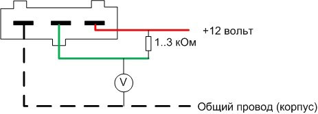
Here you can also replace the LED with a multimeter. Turning the crankshaft of the car manually, you can observe periodic flashes of the LED or changes in the output voltage from zero to approximately the voltage of the car's electrical system. An alternative way to check in a garage is to temporarily replace the device with a known-good spare sensor.
The Hall sensor has found wide application in household and industrial equipment. It is not difficult to check it for serviceability if there is an understanding of the principle of its operation.
Similar articles: