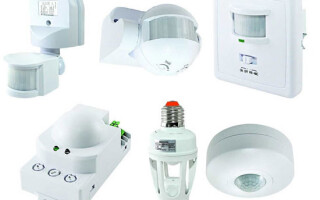
To conveniently control lighting devices and reduce the cost of using electrical energy, users are increasingly resorting to the use of automatic control devices based on motion sensors of various configurations. Installation of such devices is carried out according to certain schemes, which we will consider in this article.
Content
Selecting the location of the motion sensor
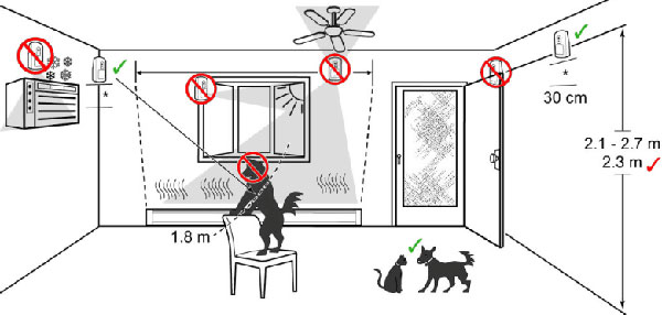
First of all, after acquiring a motion sensor, you need to decide on the installation location of this device. Choosing the right place is very important for the correct operation of the motion sensor and the prevention of false positives.
To control night lighting, a place is selected from which the sensor can cover a large part of the room. For example, to control lighting in a corridor or on a landing, it is necessary that doors from all rooms or apartments fall into the motion sensor zone. In this case, when a person enters the room from any door, the motion sensor will work correctly and turn on the light.
For a spacious room, such as a large room, hall or hall, a smart solution would be to install a ceiling sensor with a coverage of 360 degrees and a radius greater than the maximum length of the room. The installation of several motion sensors in such premises as a solution, in general, also takes place, but rather cumbersome and not convenient enough.
When installing such a control device, it is important to remember that you should not install it near devices that emit infrared or electromagnetic interference, emit steam (e.g. kettles, etc.) or thermal radiation (heaters, heating pipes, air conditioners).
It is advisable, before the final installation of the motion sensor, to test its operation in several places. This will allow you to choose the optimal installation location with accurate operation of the device.
Designation of motion sensor outputs
In order to understand how to connect a motion sensor to a lighting control circuit, you need to understand several important aspects: what voltage this type of device works with and how the sensor outputs are marked, to which the power wires and the device will be connected.
Standard motion sensors are designed to operate on 220V AC, but there are options that operate on 12V DC (for management LED strips) and radio sensors, which are powered by a battery and serve to send a signal to the control device.
The terminal marking on the device is usually made on the case itself by embossing on plastic or using special stickers. The connection diagram is also made on the case, as well as in the manual for connecting, configuring and operating this device.
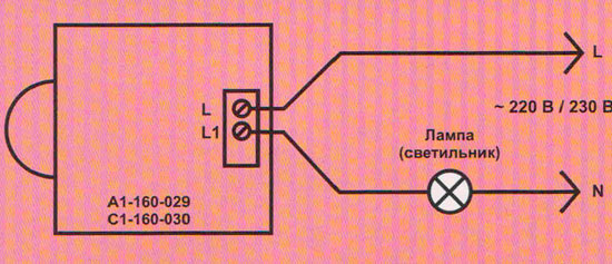
The standard designations are as follows:
- letter L the output to which the incoming phase is connected is indicated;
- letter N the output to which the neutral conductor is connected is indicated;
- L' (or another letter) denotes the outgoing phase going to the lighting fixture.
At the same time, unlike other electrical appliances, in this case it is very important not to confuse the phase and zero conductors during connection. This is due to the fact that the motion sensor, like a switch, must break the phase wire, and not zero (for safe operation, this requirement is specified in the PUE). You can determine where the phase is and where it is zero using the color marking of the conductors (usually brown or black - phase, blue - zero), but it's better to use screwdriver tester or multimeter.
Schematic wiring diagrams
Connecting a motion sensor to a circuit to control a lighting device as a whole should not cause much difficulty even for an ordinary user who is not very versed in electrics. Of course, this installation is best entrusted to a professional electrician, but to save money, you can familiarize yourself with the following: circuit diagrams and connect everything yourself.
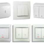
Two-wire motion sensor connection
This method of connecting the motion sensor is performed using two wires and assumes the presence of only a phase (without using zero). Such devices are often used for mounting in standard sockets to replace conventional switches or to share use of switches and motion sensors.
Such motion sensors have only two outputs: the first serves to connect the supply phase, and the second for the outgoing phase conductor to the lamp. The entire connection is made by analogy with a conventional single-gang switch without using zero.
This method is often used when introducing motion sensors into rooms that have already been renovated, as it allows you to replace key switches with a switch with a motion sensor.
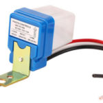
Three-wire connection
The most common scheme for connecting motion sensors is the one that has a three-wire connection scheme. They are used both indoors and outdoorswhen installing outdoors, it is important to pay attention to degree of dust and moisture protection).
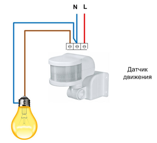
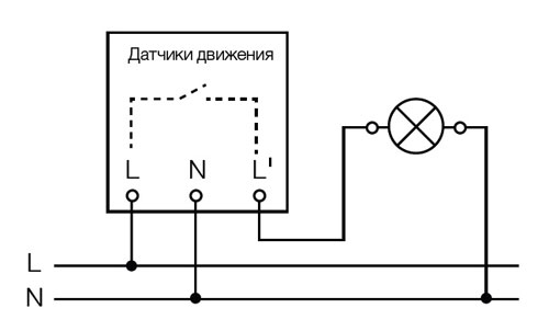
To connect three-wire sensors, it is necessary to bring phase and zero to them.The schema looks like this:
- from the junction box to the sensor, the supply phase and the neutral conductor are connected;
- from the output of the outgoing phase of the motion sensor, the conductor directly (or via junction box) reaches for the lighting device.
- also, a neutral conductor is brought to the lamp from the junction box.
Lead wires to the sensor are connected to terminals L (phase) and N (zero), and outgoing to the conclusion L’ (or another letter like A).
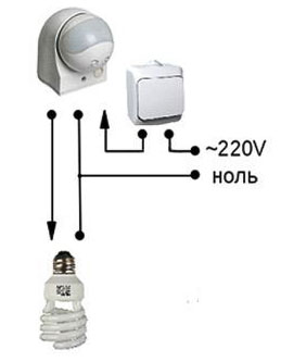
Scheme of switching on the motion sensor with a switch
The universal scheme for connecting the motion sensor includes its use in conjunction with a standard single-gang switch. The scheme of such a connection is as follows: the supply phase is connected not only to the automatic motion sensor, but also to the switch (i.e. parallel connection). From the key switch, the outgoing phase conductor is brought to the lamp, as well as the outgoing phase from the motion sensor.
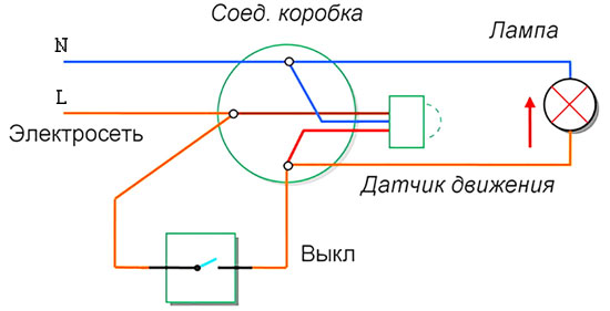
This method is very convenient for lighting control, as it allows you to turn on and off the lighting device, regardless of the time of day, as well as the health and sensitivity of the motion sensor.
You can also connect a switch in series with the motion sensor before it and turn off both the sensor and the lighting device with it. It is difficult to imagine where such a connection scheme can be used, since it has obvious disadvantages:
- When the switch is turned off, the sensor will not work and the light will not turn on automatically when motion is detected.
- When switching the one-button switch to the position "ON" - the lighting device may not turn on immediately, since it takes from 15 to 30 seconds to start the motion sensor in the operating mode.
Wiring diagram for multiple sensors
To control the light, you can connect several motion sensors. This method is used in spacious rooms or long corridors. For example, in a long corridor it is not possible to control lighting using a single sensor, since it has a limited range (usually 10-12 meters), and if there are turns, it is even more difficult to turn on the light in this way. To do this, several motion sensors are installed in the passage zones with an installation step equal to the radius of their action. In this case, a person, leaving the zone of action of one device, will certainly fall into the zone of action of another sensor and the light will not turn off.
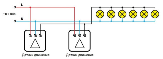
For the correct operation of lighting, apply parallel connection such motion detection devices, it does not matter their number in the circuit.
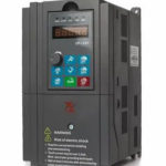
Circuit with starter or contactor
To control heavy loads, such as to control street lightingconsisting of lamps with a power of more than 1 kW, direct control using a motion sensor is not suitable - it can fail due to the large current passing through it.
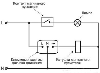
In this case, a scheme is used with the inclusion of a load using magnetic starter or contactor. The control scheme will look like this:
- load (several powerful lighting fixtures) will connect to contactor or electromagnetic starter relay;
- the motion sensor is also connected to a relay or contactor, but to control outputs.
It will work like this: when motion is detected, the sensor supplies voltage to the starter coil, the solenoid in the starter closes the contacts using electromagnetic induction and turns on the load. In this case, the motion sensor and the load are galvanically isolated and are not interconnected.
Configuring and adjusting device settings
In order for the device to correctly respond to movement and not react to interference, the movement of pets or branches outside the window, it is important not only to install it correctly, but also to correctly configure it.
Viewing angle
Some devices allow you to control the viewing angle using a special switch on the device. This makes it possible to reduce or, conversely, increase the angle of the controlled zone by the motion sensor for correct operation. Those devices that do not have viewing angle adjustment are configured by turning them in the right direction or using the wall as a limiter. Craftsmen also resort to the help of electrical tape, artificially limiting the view of the sensor by sticking its scanning screen in the right places.
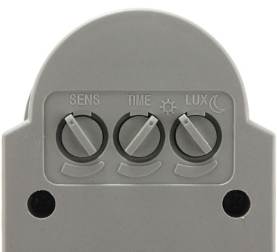
Sensitivity (SENS)
This switch allows you to reduce the number of false alarms from pets, tree branches outside the window and other factors. Adjustment for this factor starts with the minimum value of the switch, with a subsequent increase to the desired one. All this is done experimentally with mandatory testing.
Switch-off delay (TIME)
The ability to adjust the delay depends on the specific device and can be in the range from 5 seconds to 30 minutes.The setting for this parameter is based on user preferences and the purpose of the room or lighting. It works as follows: when motion is detected, the lighting turns on and then turns off only after the set delay on the device has elapsed.
Light level (LUX/DAY LIGHT)
Adjustment for this parameter is made to control the inclusion of the lighting device at a given illumination. That is, the inclusion will occur only if there is a registration of movement at the adjusted illumination. If the illumination in the room is higher, the device will not turn on. Adjustment is made from the minimum value, gradually increasing to the required value.
Installation and connection errors
The main mistakes when installing a motion sensor are the wrong choice of installation location and setting its parameters (sensitivity, illumination). If this situation occurs, the sensor may not work when a person is in the room, turn on with a delay, or when pets move. Therefore, the setup itself takes a lot of time and must take into account all the conditions in which this device will operate.
The connection of conductors itself is usually not difficult - connecting three wires according to the scheme is quite simple. The main thing here is not to confuse the phase and zero and connect conductors that do not have insulation violations and damage to the cores.
Similar articles: