Electrical installation and commissioning are always associated with measuring the characteristics of the electrical network, checking the presence of voltage and the operability of the circuits of the device or line. For these purposes, there are a huge number of different measuring instruments and testers, but the most versatile and useful device for home craftsmen and professionals is a multimeter. In this article, we will look at how to use it.
Content
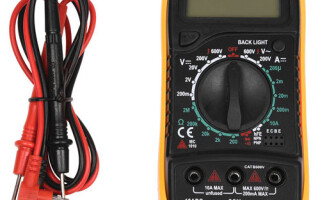
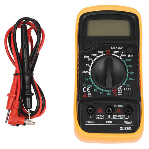
The appearance of the multimeter
multimeter is a universal instrument for measuring electrical characteristics, which combines many functions (depending on the model).In the minimum configuration, such a device consists of an ammeter, voltmeter and ohmmeter. In the most common version, it is carried out in a digital form of a portable version. Externally, it has a rectangular shape with a display and a rotary or push-button function switch. To perform measurements, two probes are connected to the multimeter (Red and black) in strict accordance with the marking on the device.
Brief description of the measured parameters and their designation
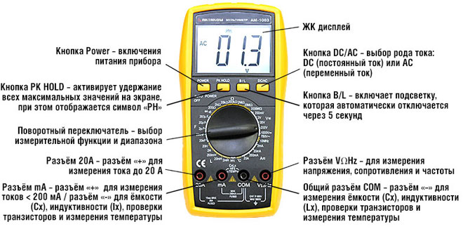
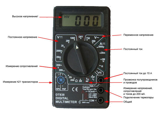
To designate parameters on multimeters, manufacturers use standard markings in English or special characters. To work with the device, it is important to know the basics of electrical engineering in order to correctly and safely carry out the necessary measurements.
Each device is divided into zones with settings for working with a certain type of electrical network voltage:
- ACV or V~ – AC voltage;
- DCV or V- – DC voltage;
- DCA or A- – direct current strength;
- Ω - resistance in a circuit section or in an electrical device.
Assignment of connectors for connecting probes
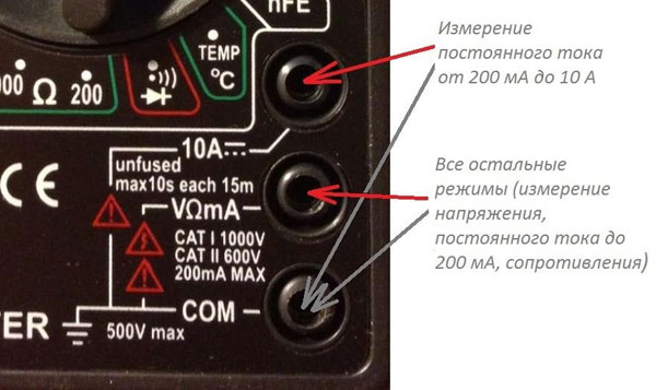
Depending on the model of the multimeter, the number of sockets for connecting probes may be different. It is necessary to connect the probes for measuring the electrical parameters of the network to the correct sockets of the device. For most measuring instruments, the socket markings are as follows:
- 10A- - for measuring direct current not exceeding 10 A (Connect the red positive lead to this socket.);
- VΩmA or VΩ, V/Ω - connect red to this socket (positive) probe when determining voltage, DC current up to 200 mA, for continuity of diodes and circuits;
- COMMOM (COM) – common socket for black (negative) probe on all types of multimeters;
- 20A – this socket does not exist on all models (most often found on expensive professional devices), the task of this socket is similar to 10A-, but with a limit of up to 20 A.
What other buttons can be
In addition to the basic settings of the multimeter, it may have additional ones. Expensive professional devices are much more functional than budget options and allow a specialist to make the following measurements:
- AC power (in the presence of current clamps);
- circuit integrity (call), that is, check the resistance signaling the results with the help of sound or light alarms, as well as indications on the display;
- testing the performance of diodes (switch ->Ι-);
- transistor parameters (connectors and buttons marked hFE);
- capacitance and inductance;
- temperature (an external sensor is used for this - usually a thermocouple).
- frequencies (Hz).
Some models have additional functions for indicating and ensuring work with the device: backlight, auto power off and battery saving mode, recording results (button hold) and writing to the device memory, selection of measurement limits and indication of overload and low battery. For safe operation with a multimeter, it is important that the device has some protection in case of incorrect selection of the measurement limit or mode of operation. Typically, this protection is provided by fuses and circuit breakers. Most high-quality devices from responsible manufacturers have such protection.
How to measure voltage
For a person who has certain skills and knowledge in electrical engineering, it will not be difficult to make measurements with a multimeter. For those who have never worked with this type of device, below is how to use a standard multimeter.
Important! All work must be carried out by specialists or people with certain skills in electrical engineering. Remember that electric shock is life-threatening!
Constant pressure
Using this mode, the voltage of batteries, batteries and car accumulators is measured. Most control circuits in modern process control systems have a potential of 24 V DC.
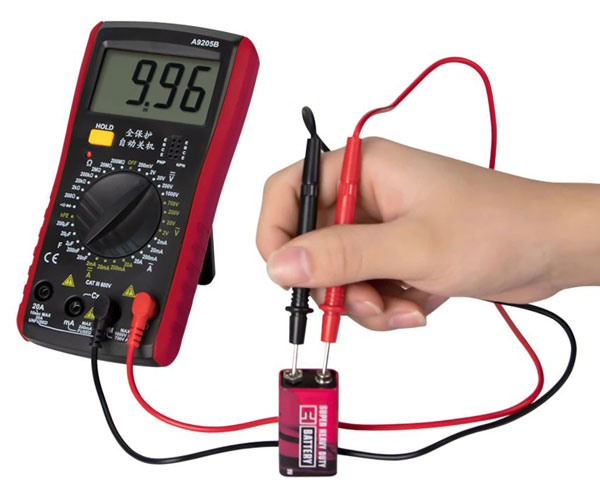
In order to perform a measurement in this mode, it is necessary to move the device to the DCV position, while measuring (if you do not know the approximate voltage) it is best to start with the maximum value of the switch, gradually decreasing the range until the desired dimension is obtained. If the measurement result is displayed with a “minus” sign on the device screen, then the polarity of the probes connection has been violated (this means "minus" was connected to the "plus" of the circuit in which the measurement is made, and "plus" to "minus").
As for the dimension, everything is simple here: if, for example, the number 003 is displayed on the screen, then it means that it is necessary to reduce the measurement range. By gradually reducing the voltage value with the switch, 03, 3 will be displayed.
If the display shows the number "1" or another incomprehensible number, then most likely the operating mode is incorrectly selected or it is necessary to increase the upper limit of the measured voltage.In other words, the measured voltage value must be less than the upper limit selected on the multimeter.
Standard values for the switch in the DC voltage zone: up to 200mV, 2V, 20V, 200V, 1000V.
Note! To measure the voltage on a thermocouple, the value of which is only a few millivolts, most likely will not work due to the error of the multimeter.
AC voltage
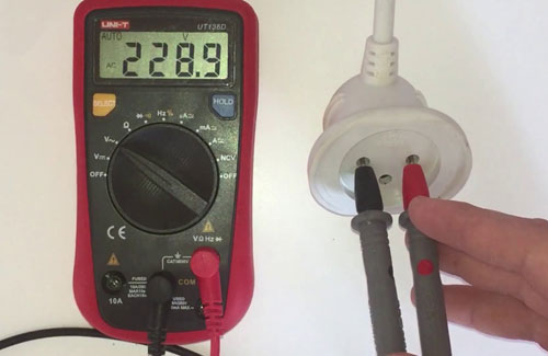
The AC voltage measurement mode is activated by moving the switch to the V~ or ACV position. This mode also has multiple ranges. Usually on standard multimeters there are two options for selecting AC voltage: up to 200 V and up to 750 V.
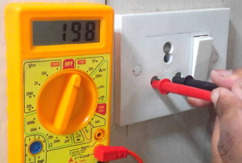
For example, to measure the voltage in a 220V household network, set the switch to 750 V and insert two probes into the outlet (in different holes). The display will show the actual voltage at the current time. Usually this value is from 210 to 230 V, other indications are already deviations from the norm.
We measure the current
To do this, you need to know what current we will measure: direct or alternating. Most standard multimeters are capable of measuring DC, but AC requires multimeters with current clamps.
D.C
To do this, move the multimeter switch to DCA mode. The red probe must be connected to the socket marked "10 A" and the black one to "COM". If the value of the measured current is up to 200 mA, then for greater accuracy of the readings, we rearrange the red probe into the 200 mA connector. In any case, in order not to burn the device, it is best to start measurements with a probe in the 10 A connector and rearrange it if necessary.We do the same with the switch: first we set the highest current, gradually reducing the range to obtain the desired maximum limit to a minimum value of 2000 microamperes.
Note! To measure direct electric current, the multimeter probes are placed in an open circuit.
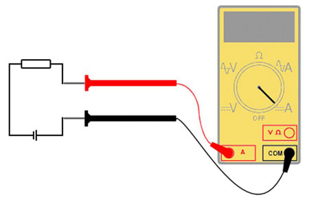
You need to know that the probes of the multimeter are connected to a break in the circuit. That is, the red probe is installed on the "plus" of the power source, and the black one to the "positive" conductor.
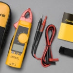
Alternating current
The value of the AC strength allows you to measure the multimeter, which has a special current clamp.
The principle of operation of current clamps is the phenomenon of electromagnetic induction. The measurement is made in a non-contact way, by placing the conductor in an electromagnet with a secondary winding. Primary current (measurable), is proportional to the secondary (which occurs on the winding). Therefore, the device easily calculates the desired value of the primary alternating current.
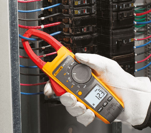
When measuring, the maximum limit is set (similar to DC measurements), the conductor is inserted into the clamps, as in the photo above, and the measured value in amperes is displayed on the screen.
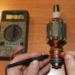
We measure resistance
To measure resistance, the switch is set to resistance (Ω) mode and the desired range is selected. One of the probes is applied to one input of the resistor, the other to the other. The display will show the resistance value. By switching the range, you can get the desired dimension of the resistance value.
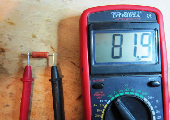
If the display shows “zero”, then the range should be reduced, and if “1”, then increase.
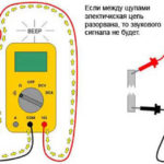
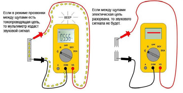
How to ring wires with a multimeter
The continuity of the wires means the definition of integrity. In fact, the multimeter determines the resistance of a closed circuit, and if this value is close to zero, then the circuit is considered closed and an audible signal is issued. Not every multimeter can ring wires with sound, but most of them can.
Continuity is a test of the integrity of the circuit. To test the wires, the multimeter is set to the desired mode. Most often, it is combined with the continuity of diodes, but can be taken out separately and marked with a bell sign. Next, one probe is applied to one end of the conductor, and the other probe to the other. In this case, a signal sounds or an indication appears on the light or on the display. If there is an indication, the circuit is not broken, if not, then the conductor is damaged or the circuit is broken.
Testing diodes, capacitors and transistors (hFE mode)
Not every device has this mode. To check the resistance of the diodes, the appropriate mode is selected and, by analogy with the continuity of the conductor, the necessary actions are performed.
To determine the parameters of capacitors and transistors, a special mode is set on the device "hFE».
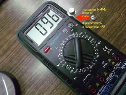
The transistors have three outputs: base, emitter and collector, which are connected to the B, E, F terminals of the multimeter. When connected correctly, the display will show the gain of the transistor.
For capacitors, the capacitance is measured by inserting the ends of the capacitor into the connectors marked Cx. In this case, the display will show the nominal value of the capacitance of the electronic component.
Similar articles: