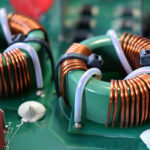
A sensor in the general sense is a device that converts one physical quantity into another, convenient for processing, transmission or subsequent conversion. As a rule, the first quantity is physical, not amenable to direct measurement (temperature, speed, displacement, etc.), and the second is an electrical or optical signal. A niche in the field of measuring instruments is occupied by sensors, the main element of which is an inductor.
Content
How the inductance sensor works and how it works
According to the principle of operation, inductive sensors are active, that is, they require an external generator to work. It provides a signal with a given frequency and amplitude to the inductor.
The current passing through the turns of the coil creates a magnetic field. If a conductive object enters the magnetic field, the parameters of the coil change.It remains only to fix this change.
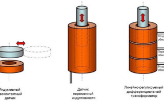
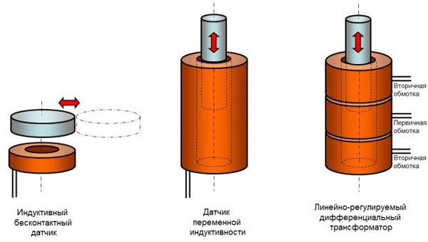
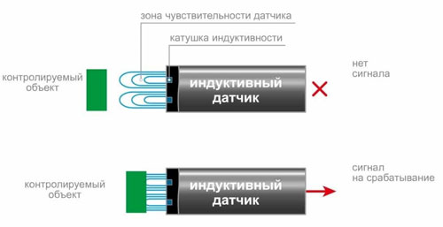
Simple non-contact sensors react to the appearance of metal objects in the near zone of the winding. This changes the impedance of the coil, this change must be converted into an electrical signal, amplify and (or) fix the passage of the threshold using a comparison circuit.
Sensors of another type respond to changes in the longitudinal position of the object that serves as the core of the coil. When the position of the object changes, it moves in or out of the coil, thereby changing its inductance. This change can be converted into an electrical signal and measured. Another version of such a sensor is when an object approaches the coil from the outside. This causes the inductance to decrease due to the ground effect.
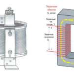
Another version of the inductive displacement sensor is a linearly adjustable differential transformer (LVDT). It is a composite coil, made in the following order:
- secondary winding 1;
- primary winding;
- secondary winding 2.
The signal from the generator is fed to the primary winding. The magnetic field created by the middle coil induces an EMF in each of the secondary (transformer principle). The core, when it moves, changes the mutual connection between the coils, changing the electromotive force in each of the windings. This change can be fixed by the measurement circuit. Since the length of the core is less than the total length of the composite coil, the position of the object can be unambiguously determined by the EMF ratio in the secondary windings.
On the same principle - a change in the inductive coupling between the windings - a turn sensor is built.It consists of two coaxial coils. The signal is applied to one of the windings, the EMF in the second depends on the mutual angle of rotation.
From the principle of operation, it is obvious that inductive sensors, regardless of design, are non-contact. They work at a distance, and do not require direct contact with the controlled object.
Advantages and disadvantages of inductive sensors
The advantages of inductive type sensors primarily include:
- design reliability;
- lack of contact connections;
- high output power, which reduces the influence of noise and simplifies the control circuit;
- high sensitivity;
- the ability to work from sources of alternating voltage of industrial frequency.
The main disadvantage of inductive type sensors is their size, weight and manufacturing complexity. For winding coils with the given parameters, special equipment is required. Also, the need to accurately maintain the amplitude of the signal from the master oscillator is considered a minus. When it changes, the area of sensitivity also changes. Since the sensors operate only on alternating current, maintaining the amplitude becomes a certain technical problem. Directly (or through a step-down transformer) it will not be possible to connect the sensor to a household or industrial network - in it, voltage fluctuations in amplitude or frequency can even reach 10% in normal mode, which makes the measurement accuracy unacceptable.
Also, the measurement accuracy can be affected by:
- third-party magnetic fields (shielding of the sensor is impossible based on the principle of its operation);
- third-party EMF pickups in supply and measuring cables;
- manufacturing errors;
- sensor characteristic error;
- backlashes or deformations at the sensor installation site that do not affect the overall performance;
- dependence of accuracy on temperature (the parameters of the winding wire change, including its resistance).
The inability of inductance sensors to respond to the appearance of dielectric objects in their magnetic field can be attributed to both advantages and disadvantages. On the one hand, this limits the scope of their application. On the other hand, it makes it insensitive to the presence of dirt, grease, sand, etc. on the monitored objects.
Knowledge of the shortcomings and possible limitations in the operation of inductive sensors allows rational use of their advantages.
Scope of inductive sensors
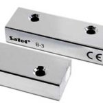
Inductive proximity sensors are often used as limit switches. Such devices have become widespread:
- in security systems, as sensors for unauthorized opening of windows and doors;
- in telemechanics systems, as sensors of the final position of units and mechanisms;
- in everyday life in the schemes for indicating the closed position of doors, shutters;
- for counting objects (for example, moving along the conveyor belt);
- to determine the speed of rotation of the gears (each tooth, passing by the sensor, creates an impulse);
- in other situations.
Angle encoders can be used to determine the rotation angles of shafts, gears and other rotating components, as well as absolute encoders. Also, such devices can be used in machine tools and robotic devices along with linear position sensors. Where you need to know exactly the position of the nodes of the mechanisms.
Practical examples of the implementation of inductive sensors
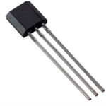
In practice, the designs of inductive sensors can be implemented in different ways. The simplest execution and inclusion is for a two-wire single sensor, which monitors the presence of metal objects in its sensitivity zone. Such devices are often made on the basis of an E-shaped core, but this is not a fundamental point. Such an implementation is easier to manufacture.
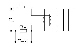
When the coil resistance changes, the current in the circuit and the voltage drop across the load change. These changes can be committed. The problem is that the load resistance becomes critical. If it is too large, then the changes in current when a metal object appears will be relatively small. This reduces the sensitivity and noise immunity of the system. If it is small, then the current in the circuit will be large, a more resistant sensor will be required.
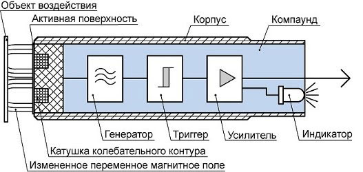
Therefore, there are designs in which the measurement circuit is built into the sensor housing. The generator generates pulses that feed the inductor. When a certain level is reached, the trigger fires, flipping from state 0 to 1 or vice versa. The buffer amplifier amplifies the signal in terms of power and (or) voltage, lights (extinguishes) the LED and outputs a discrete signal to the external circuit.
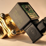
The output signal can be formed:
- by electromagnetic or solid state relay – zero or one voltage level;
- "dry contact" electromagnetic relay;
- open collector transistor (structures n-p-n or p-n-p).
In this case, three wires are required to connect the sensor:
- food;
- common wire (0 volt);
- signal wire.
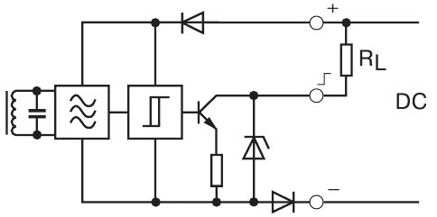
Such sensors can also be powered by DC voltage. Pulses to the inductance they are formed by means of an internal generator.
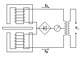
Differential encoders are used for position monitoring. If the controlled object is symmetrical with respect to both coils, the current through them is the same. When any winding is shifted towards the field, an imbalance occurs, the total current ceases to be equal to zero, which can be recorded by an indicator with an arrow in the middle of the scale. The indicator can be used to determine both the magnitude of the shift and its direction. Instead of a pointer device, you can use a control scheme that, upon receipt of information about a change in position, will issue a signal, take measures to align the object, make adjustments to the technological process, etc.
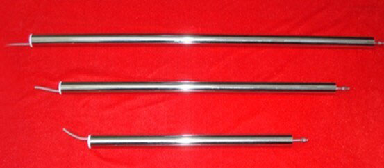
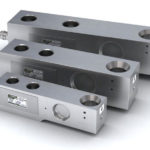
Sensors made according to the principle of linearly adjustable differential transformers are produced in the form of complete structures, which are a frame with primary and secondary windings and a rod moving inside (it can be spring-loaded). Wires are brought out to send a signal from the generator and remove the EMF from the secondary windings. A controlled object can be mechanically attached to the rod. It can also be made of a dielectric - only the position of the stem matters for measurement.
Despite certain inherent shortcomings, the inductive sensor closes many areas associated with non-contact detection of objects in space.Despite the constant development of technology, this type of device will not leave the market for measuring devices in the foreseeable future, because its operation is based on the fundamental laws of physics.
Similar articles: