The electrical diagram is a detailed drawing indicating all electronic components and accessories that are interconnected by conductors. Knowledge of the principle of functioning of electrical circuits is the key to a well-assembled electrical appliance. That is, the assembler must know how electronic elements are indicated on the diagram, which icons, alphabetic or numeric characters correspond to them. In the material, we will understand the key notation and the basics of how to learn to read electrical circuit diagrams.
Any electrical circuit includes a number of parts, consisting of smaller elements. Let's take an electric iron as an example, which contains a heating element inside, a temperature sensor, light bulbs, fuses, and also has a wire with a plug. In other household appliances, an advanced configuration is provided with circuit breakers, electric motors, transformers, and between them there are connectors for the full interaction of the components of the device and the fulfillment of the purpose of each of them.
Therefore, the problem often arises of how to learn how to decipher electrical circuits that contain graphic symbols.The principles of reading diagrams are important for those who are engaged in electrical installation, repair of household appliances, and connection of electrical devices. Knowledge of the principles of reading electrical circuits is necessary in order to understand the interaction of elements and the functioning of devices.
Content
Types of electrical circuits
All electrical circuits are presented in the form of an image or drawing, where, along with the equipment, the links of the electrical circuit are indicated. The circuits differ in purpose, on the basis of which a classification of different electrical circuits has been developed:
- primary and secondary circuits.
Primary circuits are created to supply the main electrical voltage from the current source to consumers. They generate, transform and distribute electricity during transmission. Such circuits assume the presence of a main circuit and circuits for various needs.
In secondary circuits, the voltage is not higher than 1 kW; they are used to provide automation, control and protection tasks. Thanks to the secondary circuits, the consumption and metering of electricity is monitored;
- single line, full line.
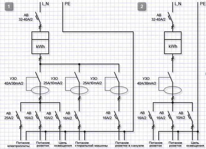
Full line diagrams are designed for use in three-phase circuits and display connected devices on all phases.
Single-line diagrams show only fixtures in the middle phase;
- fundamental and assembly.
The basic general electrical circuit implies the indication of only key elements, it does not indicate minor details. Thanks to this, the schemes are simple and understandable.
The wiring diagrams show a more detailed image, since it is such diagrams that are used for the actual installation of all elements of the electrical network.
Detailed diagrams indicating secondary circuits help to highlight auxiliary electrical circuits, sections with separate protection.
Symbols in the diagrams
Electrical circuits consist of elements and components that ensure the flow of electric current. All elements are divided into several categories:
- devices that generate electricity - power supplies;
- converters of electric current into other types of energy - act as consumers;
- parts responsible for the transmission of electricity from the source to the devices. Also included in this category are transformers and stabilizers that ensure the stability of the voltage in the network.
Each element has a specific graphic designation on the diagram. In addition to key designations, the diagrams indicate power transmission lines. Sections of the electrical circuit through which the same current flows are called branches, and at the points of their connection, dots are placed on the diagram to indicate connecting nodes.
The circuit of the electrical circuit assumes a closed path for the movement of electric current along several branches. The simplest circuit consists of a single circuit, and for more complex devices, circuits with several circuits are provided.
On the electrical diagram, each element and connection corresponds to an icon or designation. To display insulation pins, single-line and multi-line diagrams are used, the number of lines in which is determined by the number of pins.Sometimes, for ease of reading and understanding the circuits, mixed drawings are used, for example, the stator insulation is described in detail, and the rotor insulation is described in general terms.
The designations of transformers in electrical circuits are drawn in a general or expanded form, using single-line and multi-line methods. Directly from the detailing of the image depends on the method of displaying devices on the diagram, their conclusions, connections and nodes. So, in current transformers, the primary winding is reflected by a thick line with dots. The secondary winding can be displayed as a circle in the standard circuit, or two semicircles in the case of an expanded circuit.
Other elements are displayed on the diagrams with the following symbols:
- contacts are divided into make, break and switches, which are indicated by different signs. If necessary, the contacts can be specified in mirror image. The base of the moving part is indicated as an open dot;
- switches - their base corresponds to a dot, and for automatic switches, the release category is drawn. The switch for open installation, as a rule, has a separate designation;
- fuses, constant resistance resistors and capacitors. Safety elements are shown as a rectangle with taps, fixed resistors can be marked with or without taps. The moving contact is drawn with an arrow. Electrolytic capacitors are designated according to polarity;
- semiconductors. Simple diodes with a pn junction are shown as a triangle and a cross circuit line.The triangle represents the anode and the line represents the cathode;
- incandescent lamp and other lighting elements usually denote
Understanding these icons and symbols makes reading electrical diagrams easy. Therefore, before proceeding with the electrical installation or disassembly of household appliances, we recommend that you familiarize yourself with the basic symbols.
How to read electrical diagrams correctly
The schematic diagram of the electrical circuit displays all the parts and links between which current flows through the conductors. Such circuits are the basis for the design of electrical devices, so reading and understanding electrical circuits is a must for any electrician.
A competent understanding of circuits for beginners makes it possible to understand the principles of their compilation and the correct connection of all elements in an electrical circuit to achieve the expected result. In order to correctly read even complex diagrams, it is necessary to study the main and secondary images, the symbols of the elements. Conventional signs indicate the general configuration, specifics and purpose of the part, which allows you to create a complete picture of the device when reading the circuit.
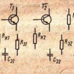
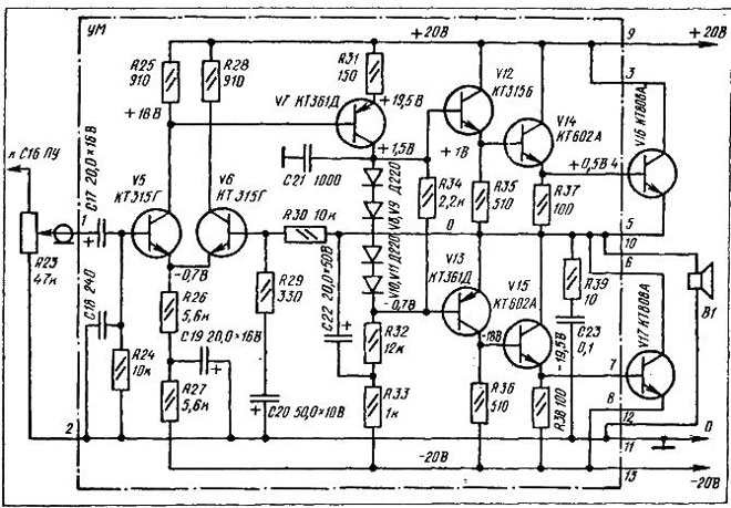
You can start familiarization with the circuits with small devices, such as capacitors, speakers, resistors. More difficult to understand are the circuits of semiconductor electronic parts in the form of transistors, triacs, microcircuits. So in bipolar transistors there are at least three outputs (base, collector and emitter), which requires more symbols. Due to the large number of different signs and drawings, it is possible to identify the individual characteristics of the element and its specificity.The notation encodes information that allows you to find out the structure of the elements and their special characteristics.
Often, symbols have auxiliary clarifications - next to the icons there are Latin letter designations for detailing. It is also recommended that you familiarize yourself with their meanings before starting work with diagrams. Also, next to the letters there are often numbers that display the numbering or technical parameters of the elements.
So, in order to learn how to read and understand electrical circuits, you need to familiarize yourself with the symbols (drawings, alphabetic and numeric characters). This will allow you to obtain information from the diagram regarding the structure, design and purpose of each element. That is, to understand the circuits, you need to study the basics of radio engineering and electronics.
Similar articles: