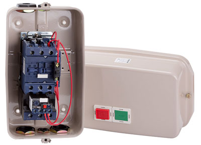
A magnetic starter, or an electromagnetic contactor, is a switching device that switches powerful DC and AC currents. Its role is to systematically turn on and off sources of electricity.
Content
Purpose and device
Magnetic starters are built into electrical circuits for remote start, stop and protection of electrical equipment, electric motors. The work is based on the use of the principle of electromagnetic induction.
The design is based on a thermal relay and a contactor combined into one device. Such a device is able to work, including in a three-phase network.
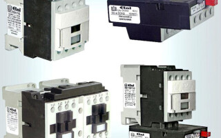
Such devices are gradually being replaced from the market by contactors. In their design and technical characteristics, they are no different from starters, and it is possible to distinguish them only by name.
Between themselves, they differ in the supply voltage of the magnetic coil.It comes in 24, 36, 42, 110, 220, 380 watts AC. Devices are produced with a coil for direct current. Their use in an alternating current network is also possible, for which a rectifier is needed.
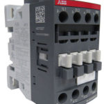
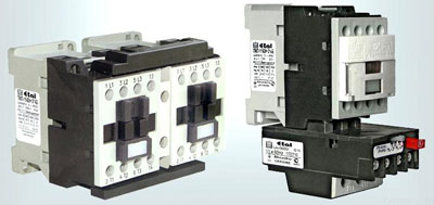
The design of the starter is usually divided into upper and lower parts. In the upper part there is a movable contact system combined with an arc chute. It also houses the moving part of the electromagnet, mechanically connected to the power contacts. All this constitutes a movable contact circuit.
At the bottom there is a coil, the second half of the electromagnet and a return spring. The return spring returns the upper half to its original state after the coil is de-energized. This is how the starter contacts break.
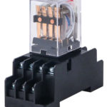
Contactors are:
- normally closed. Contacts are closed, and power is supplied constantly, shutdown occurs only after the starter is triggered.
- Normally open. The contacts are closed and power is supplied while the starter is operating.
The second option is the most common.
Principle of operation
The principle of operation of a magnetic starter is based on the phenomenon of electromagnetic induction. If no current flows through the coil, then there is no magnetic field in it. This causes the spring to mechanically repel the moving contacts. As soon as the power supply of the coil is restored, magnetic fluxes arise in it, compressing the spring and attracting the armature to the fixed part of the magnetic circuit.
Since the starter works only under the influence of electromagnetic induction, the opening of contacts occurs during power outages and when the voltage in the network drops by more than 60% of the nominal value. When the voltage is restored again, the contactor does not turn on by itself. To activate it, you need to press the "Start" button.
If it is necessary to change the direction of rotation of an asynchronous motor, reversing devices are used. The reversal is due to 2 contactors activated in turn. When the contactors are switched on at once, a short circuit occurs. To avoid such situations, a special lock is included in the design.
Varieties and types
Starters manufactured according to Russian standards are divided into 7 groups depending on the rated load. The zero group withstands a load of 6.3 A, the seventh group - 160 A.
This must be remembered when choosing magnetic starters.
The classification of foreign analogues may differ from that adopted in Russia.
It is necessary to be guided by the type of execution:
- Open. Suitable for installation in closed cabinets or places isolated from dust.
- Closed. Installed separately, in dust-free rooms.
- Dust and splash proof. Can be installed anywhere, including outdoors. The main condition is the installation of a visor that protects from sunlight and rain.
By type, the electromagnetic starter can be selected according to the following parameters:
- Standard versions in which the starter is energized with further core attraction and contact activation.In this case, depending on whether the starter is normally closed or normally open, the electrical equipment is switched on or off.
- Reverse modifications. Such a device is a reverse with electromagnets. This design eliminates the simultaneous inclusion of 2 devices.
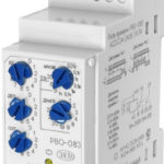
In the marking of the magnetic starter, its technical characteristics are encrypted. The designation is placed on the case and may contain the following values:
- Instrument series.
- Rated current, the designation of which is entered in the range of values.
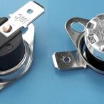
- The presence and design of the thermal relay. There are 7 degrees.
- Degree of protection and control buttons. There are 6 positions in total.
- The presence of additional contacts and their varieties.
- Compliance of fasteners with standard mounting frames.
- Climate compliance.
- Accommodation options
- Wear resistance.
There are several options for installing magnetic contactors in control systems, from the simplest control of electric motors to installation with holding the contact button, or reverses.
Wiring diagram for 220 V
Any electrical connection diagram contains 2 circuits, including for a single-phase network. The first is power, through which power is supplied. The second is a signal. With its help, the operation of the device is controlled.
The connected contactor, thermal relay and control buttons make up a single device, which is marked as a magnetic starter on the diagram. It ensures the proper functioning and safety of electric motors in various operating modes.
Contacts for connecting the power supply of the device are located in the upper part of the case. They are designated A1 and A2. So, for a 220 V coil, 220 V voltage is supplied. The order of connecting "zero" and "phase" does not matter.
On the bottom of the case there are several contacts marked L1, L2, L3. The power supply for the load is connected to them. It doesn’t matter whether it is constant or variable, the main thing is a limit of 220 V. The voltage is removed from the contacts T1, T2, T3.
Wiring diagram for 380 V
The standard scheme is used in cases where the engine needs to be started. Management is carried out using the "Start" and "Stop" buttons. Instead of a motor, any load can be connected through magnetic starters.
In the case of power supply from a three-phase network, the power section includes:
- Three-pole automatic switch.
- Three pairs of power contacts.
- Three-phase asynchronous electric motor.
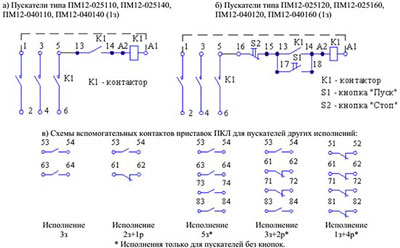
The control circuit is powered by the first phase. It also includes the "Start" and "Stop" buttons, a coil and an auxiliary contact connected in parallel to the "Start" button.
When you press the "Start" button, the first phase enters the coil. After that, the starter is activated, and all contacts are closed. The voltage passes to the lower power contacts and is fed through them to the electric motor.
The circuit may differ depending on the nominal voltage of the coil and the voltage of the mains used.
Connection via button post
The circuit connecting magnetic starters through a push-button post provides for the use of an analog adapter. Contact blocks come in 3 or 4 outputs. When connecting, it is necessary to determine the direction of the cathode.Then the contacts are connected through the switch. For this, a two-channel trigger is used.
If you connect a device with automatic switches, then an electronic regulator is used for them. Blocks can be located on the controller. Most often there are devices with broadband connectors.
Similar articles: