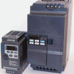
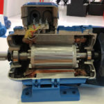
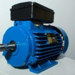
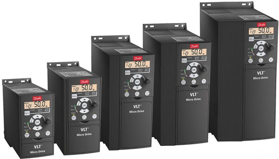
Frequency converters are used to connect various electric motors and allow you to adjust such characteristics as the rotor speed, shaft torque and protect against overloads and overheating. Also, such devices make it possible to connect three-phase equipment to a single-phase system without power loss and overheating of the motor windings.
Content
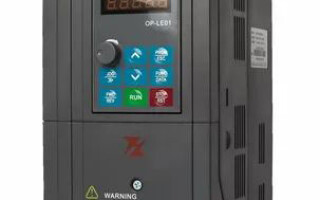
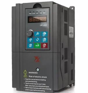
Varieties of frequency converters
Modern frequency converters differ in a variety of schemes that can be grouped into several categories:
- High-voltage two-transformer
The principle of operation of such a device is to sequentially convert the voltage using a step-down and step-up transformer, frequency conversion with a low-voltage converter, and smoothing peak overvoltages at the output using a sine-wave filter. The operation scheme is as follows: a supply voltage of 6000 V is supplied to a step-down transformer and 400 (660) V is obtained at its output, then it is supplied to a low-voltage converter and, after changing the frequency, is supplied to a step-up transformer to increase the voltage value to the initial one.
- Thyristor converters
Such devices consist of multilevel frequency converters based on thyristors. Structurally, they consist of a transformer (providing a decrease in the supply voltage), diodes (for straightening) and capacitors (for smoothing). Also, to reduce the level of higher harmonics, multipulse circuits are used.
Thyristor converters have a high efficiency of up to 98% and a large output frequency range of 0-300 Hz, which is a positive and demanded characteristic for modern equipment.
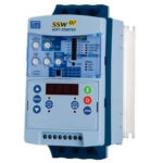
- Transistor frequency converters
Such frequency converters are high-tech devices that are assembled on transistors of various types. Structurally, they have transistor inverter cells and a multi-winding dry transformer of a special design. Such a converter is controlled using a microprocessor, which allows you to fine-tune the operation of the equipment and control the entire process of the operation of various engines. Transistor frequency converters, as well as thyristor ones, have a high efficiency and a wide frequency control range.
How to connect a frequency converter
To connect the frequency converter to the equipment, first of all, you need to make sure that the characteristics of such a device are suitable for working with a particular electric motor.It is also important that the mains voltage allows the use of this frequency converter.
When installing and connecting the emergency, it is necessary that the operating conditions correspond to the class of protection against moisture and dust, and that all distances from the moving parts of machines and mechanisms, from human walkways and electrical equipment and equipment are maintained.
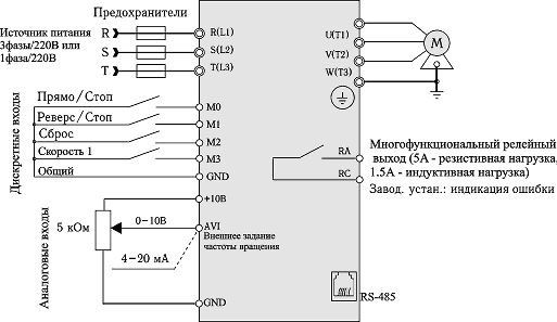
FC connection diagram
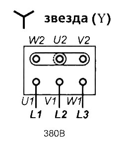
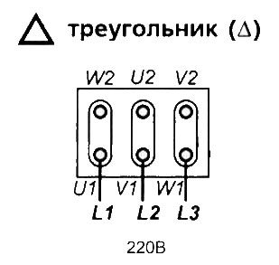
Frequency converters are available for both three-phase and single-phase networks. At the same time, a three-phase frequency converter can also be connected to a single-phase network according to the “triangle” scheme, which is additionally equipped with a special capacitor unit (at the same time, the power drops significantly and the efficiency of the device decreases.). The connection of a three-phase converter in the corresponding network is carried out according to the "star" scheme.
The frequency converter can be controlled using contactors, embedded in various relay circuits, microprocessor controllers and computer equipment, as well as manually. Therefore, when connecting automated systems, the participation of specialists in setting up such equipment is required.
Note! The frequency converter may have additional settings performed using DIP switches, as well as firmware.
The principle of connecting frequency converters is generally the same, but may differ slightly for different models. Therefore, the right decision would be to study the instructions before connecting, compare the characteristics of the devices and make sure that the device is connected according to the scheme proposed by the manufacturer.
For three-phase electric motor
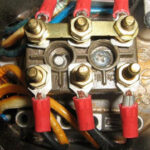
For a three-phase electric motor, the connection principle is as follows: phase conductors are connected to the terminal blocks at the output of a three-phase frequency converter, and phases of the supply voltage are connected to the input. In this case, the "star" connection in the motor is always implemented. When connecting a three-phase motor through a frequency converter to a single-phase network, a "triangle" scheme is used.
For single phase motor
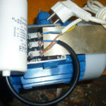
For single-phase electric motor it is necessary to connect the phase and neutral conductors to the frequency converter, and the motor windings are connected to the corresponding terminals at the output of the frequency converter. For example, winding L1 will be connected to terminal A of the converter, winding L2 to terminal B, and common wire to terminal C. If applicable capacitor motor, then from the frequency converter the phase is connected to the motor, and the capacitor provides a phase shift.
In all cases, when connecting frequency converters and electric motors, protection devices should always be used: circuit breakers and RCDs designed for high inrush currents, and it is also necessary to connect the ground conductor to the device cases. It is also important to pay attention to the cross section of the conductors of the electrical cable that will be connected - the cross section must correspond to the parameters of the connected frequency converter and load.
Similar articles: