Modulation is a non-linear electrical process in which the parameters of one signal (carrier) are changed using another signal (modulating, informational). In communication technology, frequency, amplitude, and phase modulation is widely used. In power electronics and microprocessor technology, pulse-width modulation has become widespread.
Content
What is PWM (Pulse Width Modulation)
With pulse-width modulation of the original signal, the amplitude, frequency and phase of the original signal remain unchanged. The duration (width) of the rectangular pulse is subject to change under the action of the information signal. In the English technical literature, it is abbreviated as PWM - pulse-width modulation.
How PWM works
The pulse width modulated signal is formed in two ways:
- analog;
- digital.
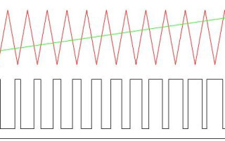
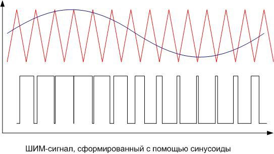
With the analog method of creating a PWM signal, a carrier in the form of a sawtooth or triangular signal is fed to an inverting comparator input, and information - on non-inverting. If the instantaneous carrier level is higher than the modulating signal, then the output of the comparator is zero, if lower - one. The output is a discrete signal with a frequency corresponding to the frequency of the carrier triangle or saw, and a pulse length proportional to the level of the modulating voltage.
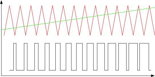
As an example, the pulse width modulation of a triangular signal is linearly increasing. The duration of the output pulses is proportional to the level of the output signal.
Analog PWM controllers are also available in the form of ready-made microcircuits, inside which a comparator and a carrier generation circuit are installed. There are inputs for connecting external frequency-setting elements and supplying an information signal. A signal is removed from the output that controls powerful foreign keys. There are also inputs for feedback - they are needed to maintain the set control parameters. Such, for example, is the TL494 chip. For cases where the power of the consumer is relatively small, PWM controllers with built-in keys are available. The internal key of the LM2596 microcircuit is designed for current up to 3 amperes.
The digital method is carried out using specialized microcircuits or microprocessors. The pulse length is controlled by the internal program. Many microcontrollers, including the popular PIC and AVR, have a built-in module for hardware implementation of PWM “on board”, to receive a PWM signal, you need to activate the module and set its operation parameters.If such a module is not available, then PWM can be organized purely by software, this is not difficult. This method gives more power and freedom through flexible use of outputs, but uses more controller resources.
Characteristics of the PWM signal
The important characteristics of the PWM signal are:
- amplitude (U);
- frequency (f);
- duty cycle (S) or duty cycle D.
The amplitude in volts is set depending on the load. It must provide the rated supply voltage of the consumer.
The frequency of the signal modulated by the pulse width is selected from the following considerations:
- The higher the frequency, the higher the control accuracy.
- The frequency must not be lower than the response time of the device controlled by PWM, otherwise noticeable ripples of the controlled parameter will occur.
- The higher the frequency, the higher the switching losses. It arises from the fact that the switching time of the key is finite. In the locked state, all the supply voltage drops on the key element, but there is almost no current. In the open state, the full load current flows through the key, but the voltage drop is small, since the throughput resistance is a few ohms. In both cases, the power dissipation is negligible. The transition from one state to another occurs quickly, but not instantly. In the process of unlocking-locking, a large voltage drops on a partially open element and at the same time a significant current flows through it. At this time, the dissipated power reaches high values. This period is short, the key does not have time to warm up significantly.But with an increase in the frequency of such time intervals per unit of time, it becomes more, and heat losses increase. Therefore, to build keys, it is important to use fast elements.
- When driving electric motor the frequency has to be taken away from the area audible to a person - 25 kHz and higher. Because at a lower PWM frequency, an unpleasant whistle occurs.
These requirements are often in conflict with each other, so the choice of frequency in some cases is a compromise.
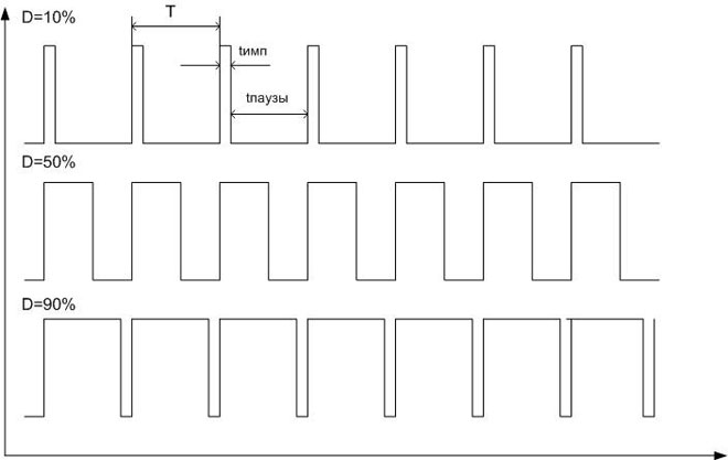
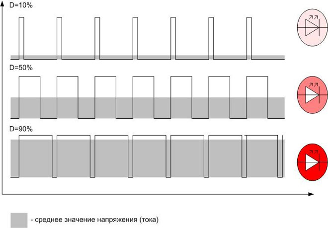
The modulation value characterizes the duty cycle. Since the pulse repetition rate is constant, the duration of the period is also constant (T=1/f). The period consists of an impulse and a pause, having a duration, respectively, timp and tpauses, and timp+tpauses=T. The duty cycle is the ratio of the pulse duration to the period - S \u003d timp/T. But in practice it turned out to be more convenient to use the reciprocal value - the fill factor: D=1/S=T/timp. It is even more convenient to express the fill factor as a percentage.
What is the difference between PWM and SIR
In foreign technical literature there is no difference between pulse-width modulation and pulse-width regulation (PWR). Russian specialists are trying to distinguish between these concepts. In fact, PWM is a type of modulation, that is, changes in the carrier signal under the action of another, modulating one. The carrier signal acts as a carrier of information, and the modulating signal sets this information. And pulse-width regulation is the regulation of the load mode using PWM.
Reasons and applications of PWM
The principle of pulse width modulation is used in speed controllers of powerful asynchronous motors. In this case, the adjustable frequency modulating signal (single-phase or three-phase) is generated by a low-power sine wave generator and superimposed on the carrier in an analog way. The output is a PWM signal, which is fed to the keys of the required power. Then you can pass the resulting sequence of pulses through a low-pass filter, for example, through a simple RC circuit, and select the original sinusoid. Or you can do without it - filtration will occur naturally due to the inertia of the engine. Obviously, the higher the carrier frequency, the more the output waveform is close to the original sinusoid.
A natural question arises - why it is impossible to amplify the signal of the generator immediately, for example, using powerful transistors? Because a regulating element operating in a linear mode will redistribute power between the load and the key. In this case, significant power is wasted on the key element. If a powerful control element operates in a key mode (trinistor, triac, RGBT transistor), then the power is distributed over time. Losses will be much lower, and efficiency will be much higher.
In digital technology, there is no particular alternative to pulse-width regulation. The signal amplitude is constant there, the voltage and current can be changed only by modulating the carrier along the pulse width and subsequently averaging it. Therefore, PWM is used to regulate voltage and current on those objects that can average the pulse signal. Averaging occurs in different ways:
- due to load inertia.Thus, the thermal inertia of thermoelectric heaters and incandescent lamps allows the regulated objects not to noticeably cool down in the pauses between pulses.
- Due to the inertia of perception. The LED has time to go out from pulse to pulse, but the human eye does not notice this and perceives it as a constant glow with varying intensity. This principle is used to control the brightness of dots of LED monitors. But an inconspicuous blinking with a frequency of several hundred hertz is still present and causes eye fatigue.
- due to mechanical inertia. This property is used in the control of brushed DC motors. With a correctly selected frequency of regulation, the motor does not have time to slow down in dead pauses.
Therefore, PWM is used where the average value of voltage or current plays a decisive role. In addition to the common cases mentioned, the PWM method regulates the average current in welding machines and battery chargers, etc.
If natural averaging is not possible, in many cases this role can be taken over by the already mentioned low-pass filter (LPF) in the form of an RC chain. For practical purposes, this is enough, but it must be understood that it is impossible to isolate the original signal from the PWM using a low-pass filter without distortion. After all, the PWM spectrum contains an infinite number of harmonics that will inevitably fall into the filter's passband. Therefore, one should not build illusions about the shape of the reconstructed sinusoid.
Very efficient and effective PWM RGB LED control. This device has three p-n junctions - red, blue, green.By changing separately the brightness of the glow of each channel, you can get almost any color of the LED glow (with the exception of pure white). The possibilities for creating lighting effects with PWM are endless.
The most common application of a pulse width modulated digital signal is to control the average current or voltage flowing through a load. But non-standard use of this type of modulation is also possible. It all depends on the imagination of the developer.
Similar articles: