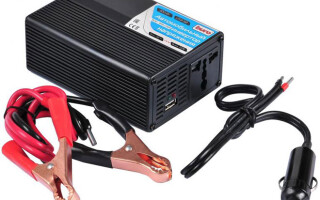
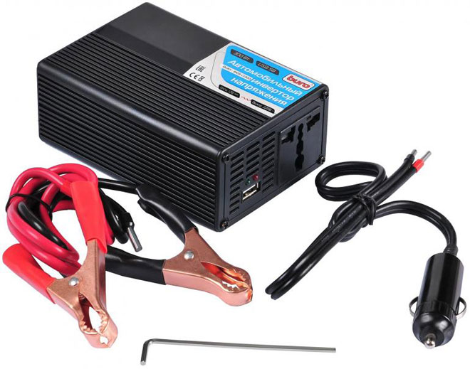
A voltage converter from 12 to 220 V is used where there is a need to connect electrical devices that consume standard mains current to an alternating voltage source. In many cases, this network is unavailable. The use of an autonomous gasoline generator requires compliance with the rules for its maintenance: constant monitoring of the level of working fuel, ventilation. The use of converters complete with car batteries allows you to solve the problem in the best way.
Content
Purpose and principle of operation
What is a voltage converter. This is the name of an electronic device that changes the magnitude of the input signal. It can be used as a step up or step down device. The input voltage after conversion can change both its magnitude and frequency.Such devices that change the DC voltage (convert it) into an AC output signal are called inverters.
Voltage converters are used both as a stand-alone device that supplies consumers with AC energy, and can be part of other products: systems and uninterruptible power supplies, devices for increasing direct voltage to the required value.
Inverters are harmonic oscillation voltage generators. A DC source using a special control circuit creates a mode of periodic polarity switching. As a result, an AC voltage signal is generated at the output contacts of the device to which the load is connected. Its value (amplitude) and frequency are determined by the elements of the converter circuit.
The control device (controller) sets the switching frequency of the source and the shape of the output signal, and its amplitude is determined by the elements of the output stage of the circuit. They are rated for the maximum power the load will draw on the AC circuit.
The controller is also used to control the magnitude of the output signal, which is achieved by controlling the duration of the pulses (increasing or decreasing their width). Information about changes in the value of the output signal at the load enters the controller through the feedback circuit, on the basis of which a control signal is generated in it to save the necessary parameters. This technique is called PWM (pulse width modulation) signals.
In the circuits of power output keys of a 12V voltage converter, powerful composite bipolar transistors, semiconductor thyristors, and field-effect transistors can be used. Controller circuits are implemented on microcircuits, which are ready-to-use devices with the necessary functions (microcontrollers), specially designed for such converters.
The control circuit provides the sequence of operation of the keys to provide the output of the inverter with the signal necessary for the normal operation of consumer devices. In addition, the control circuit must ensure the symmetry of the half-waves of the output voltage. This is especially important for circuits that use step-up pulse transformers at the output. For them, the appearance of a constant voltage component, which can appear when the symmetry is broken, is unacceptable.
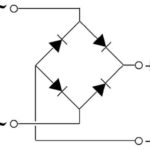
There are many options for constructing voltage inverter (VIN) circuits, but 3 main ones are distinguished from them:
- IN transformerless bridge;
- transformer IN with neutral wire;
- bridge circuit with a transformer.
Each of them finds application in its field, depending on the power source used in it and the required output power to power consumers. Each of them must be provided with elements of protection and signaling.
The undervoltage and overvoltage protection of the DC source determines the operating range of the inverters "on the input". Protection against high and low output AC voltage is necessary for the normal operation of consumer equipment. The operating range is set according to the requirements of the load being used.These types of protection are reversible, that is, when the equipment parameters are restored to normal, work can be restored.
If the protection trips due to a short circuit in the load or an excessive increase in the output current, a thorough analysis of the causes of this event is necessary before continuing to operate the equipment.
The 12V converter is the most suitable for creating a local power grid. The presence of a large number of cars and 12V DC batteries allows them to be used to meet the needs of users. Such networks can be created in a variety of places, starting from your own car. They are mobile and do not depend on the parking lot.
Varieties of converters from 12 to 220 volts
Simple converters from 12 to 220 are designed for low power consumers. The requirements for the quality of the output supply voltage and the shape of the signal are low. Their classic circuits do not use PWM microcontrollers. The multivibrator, assembled on the logic elements AND-NOT, generates electrical impulses with a repetition rate of 100 Hz. A D-flip-flop is used to create an anti-phase signal. It divides the frequency of the master oscillator by 2. An antiphase signal in the form of rectangular pulses is generated at the direct and inverse trigger outputs.
This signal, through the buffer elements on the logic elements, does NOT control the output circuit of the converter, built on key transistors. Their power determines the output power of the inverters.
Transistors can be composite bipolar and field. The sink or collector circuits include half of the primary winding of the transformer. Its secondary winding is designed for an output voltage of 220 V.Since the flip-flop divided the 100 Hz multivibrator frequency by 2, the output frequency will be 50 Hz. Such a value is necessary to power the vast majority of household electrical and radio equipment.
All elements of the circuit are powered by the vehicle's battery, using additional elements for stabilization and protection against high-frequency interference. The battery itself is also protected from them.
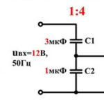
In the circuits of simple converters, elements of protection and automatic control are not provided. The frequency of the output signal is determined by the choice of the capacitance of the capacitor and the resistance of the resistor included in the master oscillator circuit. As the simplest protection against a short circuit in the load, a fuse is used in the circuit of the car battery supplying the circuit. Therefore, it is always necessary to have a spare set of fuse-links.
More powerful modern DC-to-AC converters are made according to other schemes. The PWM controller sets the operating mode. It also determines the amplitude and frequency of the output signal.
2000 W converter circuit (12 V+220 V+2000 W) uses parallel connection of power active elements in its output stages to obtain the required output power. With this circuitry, the currents of the transistors are summed up.
But a more reliable way to increase the power parameter is to combine several DC / DC converters as the input signal of a common DC / AC (direct current / alternating current) inverter, the output of which is used to connect a powerful load.Each of the DC/DC converters consists of an inverter with a transformer output and a rectifier for this voltage. There is a constant voltage of about 300 V at the output terminals. All of them are connected in parallel at the output.
It is difficult to get more than 600 W of power from one inverter. The entire circuit of the device is powered by the battery voltage.
Such circuits are provided with all types of protection, including thermal protection. Temperature sensors are mounted on the surface of the radiators of the output transistors. They generate voltage depending on the degree of heating. The threshold device compares it with the one set at the design stage and issues a signal to stop the device with the corresponding alarm. Each type of protection is equipped with its own signaling device, often sound.
Additional forced cooling is also used with the help of an air cooler installed in the case, which automatically comes into operation at the command of the corresponding thermal sensor. In addition, the case itself is a reliable heat sink, as it is made of corrugated metal.
According to the output voltage waveform
Single-phase voltage converters can be divided into two groups:
- with a pure sine wave at the output;
- with a modified sine wave.
In the inverters of the first group, the high-frequency converter creates a constant voltage. Its value is close to the amplitude of the sinusoidal signal, which is required to be obtained at the output of the device.In a bridge circuit, a component that is very close to a sinusoid in shape is separated from this DC voltage by pulse-width modulation of the controller and a low-pass filter. The output transistors open several times in each half-cycle for a time that varies according to the harmonic law.
A pure sine wave is necessary for devices that have a transformer or motor at the input. The main part of modern devices allows voltage supply, the shape of which approximately resembles a sinusoid. Particularly low requirements are imposed by products with switching power supplies.
Transformer devices
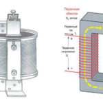
Voltage converters may contain transformers. In inverter circuits, they participate in the operation of master blocking oscillators that generate pulses that are close to rectangular in shape. As part of such a generator, a pulse transformer is used. Its windings are connected in such a way as to create a positive feedback, resulting in the creation of undamped oscillations.
The magnetic circuit (core) is made of an alloy with a high magnetic field capacity. Due to this, the transformer operates in an unsaturated mode. Various types of ferrites, permalloy have these properties.
Multivibrators have replaced transformer blocking generators. They use a modern element base and have a higher frequency stability compared to their predecessors. In addition, in multivibrator circuits, changing the operating frequency of the generator is achieved in a simple way.
In modern models of inverters, transformers operate in the output stages.Through the output from the midpoint of the primary winding to the collectors or drains of the transistors used in them, the supply voltage from the battery is supplied. The secondary windings are calculated using the transformation ratio for an alternating voltage of 220 V. This value is used to power most domestic consumers.
Similar articles: