Inductance characterizes the properties of the elements of an electrical circuit to accumulate the energy of a magnetic field. It is also a measure of the relationship between current and magnetic field. It is also compared with the inertia of electricity - just like mass with a measure of the inertia of mechanical bodies.
Content
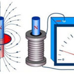
The phenomenon of self-induction
If the current flowing through a conducting circuit changes in magnitude, then the phenomenon of self-induction occurs. In this case, the magnetic flux through the circuit changes, and an emf appears at the terminals of the current loop, called the self-induction emf. This EMF is opposite to the direction of current and is equal to:
ε=-∆F/∆t=-L*(∆I/∆t)
It is obvious that the EMF of self-induction is equal to the rate of change of the magnetic flux caused by a change in the current flowing through the circuit, and is also proportional to the rate of change of the current. The coefficient of proportionality between the EMF of self-induction and the rate of change of current is called inductance and is denoted by L. This value is always positive, and has an SI unit of 1 Henry (1 H). Fractional fractions are also used - millihenry and microhenry. We can talk about an inductance of 1 Henry if a change in current by 1 ampere causes an EMF of self-induction of 1 Volt. Not only the circuit has inductance, but also a separate conductor, as well as a coil, which can be represented as a set of series-connected circuits.
The inductance stores energy, which can be calculated as W=L*I2/2, where:
- W—energy, J;
- L – inductance, H;
- I is the current in the coil, A.
And here the energy is directly proportional to the inductance of the coil.
Important! In engineering, an inductance is also a device in which an electric field is stored. The real element closest to such a definition is an inductor.
The general formula for calculating the inductance of a physical coil has a complex form and is inconvenient for practical calculations. It is useful to remember that the inductance is proportional to the number of turns, the diameter of the coil and depends on the geometric shape. Also, the inductance is affected by the magnetic permeability of the core on which the winding is located, but the current flowing through the turns is not affected. To calculate the inductance, each time you need to refer to the above formulas for a specific design. So, for a cylindrical coil, its main characteristic is calculated by the formula:
L=μ*μ*(N2*S/l),
where:
- μ is the relative magnetic permeability of the coil core;
- μ – magnetic constant, 1.26*10-6 H/m;
- N is the number of turns;
- S is the area of the coil;
- l is the geometric length of the coil.
To calculate the inductance for a cylindrical coil and coils of other shapes, it is better to use calculator programs, including online calculators.
Series and parallel connection of inductors
Inductances can be connected in series or in parallel, getting a set with new characteristics.
Parallel connection
When the coils are connected in parallel, the voltage on all elements is equal, and the currents (variables) are distributed inversely with the inductances of the elements.
- U=U1=U2=U3;
- I=I1+I2+I3.
The total inductance of the circuit is defined as 1/L=1/L1+1/L2+1/L3. The formula is valid for any number of elements, and for two coils it is simplified to the form L=L1*L2/(L1+L2). Obviously, the resulting inductance is less than the inductance of the element with the smallest value.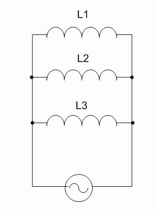
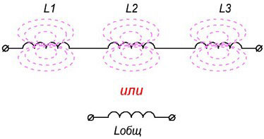
serial connection
With this type of connection, the same current flows through the circuit made up of coils, and the voltage (variable!) On each component of the circuit is distributed in proportion to the inductance of each element:
- U=U1+U2+U3;
- I=I1=I2=I3.
The total inductance is equal to the sum of all inductances, and will be greater than the inductance of the element with the largest value. Therefore, such a connection is used if necessary to obtain an increase in inductance.
Important! When connecting coils in a series or parallel battery, the calculation formulas are correct only for cases where the mutual influence of the magnetic fields of the elements on each other is excluded (shielding, long distance, etc.). If an influence exists, then the total value of the inductance will depend on the relative position of the coils.
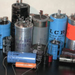
Some practical issues and designs of inductors
In practice, various designs of inductors are used. Depending on the purpose and field of application, the devices can be made in various ways, but the effects that occur in real coils must be taken into account.
Quality factor of the inductor
A real coil, in addition to inductance, has several more parameters, and one of the most important is the quality factor. This value determines the losses in the coil and depends on:
- ohmic losses in the winding wire (the greater the resistance, the lower the quality factor);
- dielectric losses in wire insulation and winding frame;
- screen loss;
- core losses.
All these quantities determine the loss resistance, and the quality factor is a dimensionless value equal to Q=ωL/Rlosses, where:
- ω = 2*π*F - circular frequency;
- L - inductance;
- ωL is the reactance of the coil.
We can approximately say that the quality factor is equal to the ratio of reactive (inductive) resistance to active. On the one hand, with increasing frequency, the numerator increases, but at the same time, due to the skin effect, the loss resistance also increases due to a decrease in the useful cross section of the wire.
screen effect
To reduce the influence of foreign objects, as well as electric and magnetic fields and the mutual influence of elements through these fields, coils (especially high-frequency ones) are often placed in a screen. In addition to the beneficial effect, shielding causes a decrease in the quality factor of the coil, a decrease in its inductance and an increase in parasitic capacitance. Moreover, the closer the screen walls are to the turns of the coil, the higher the harmful effect. Therefore, shielded coils are almost always made with the possibility of adjusting the parameters.
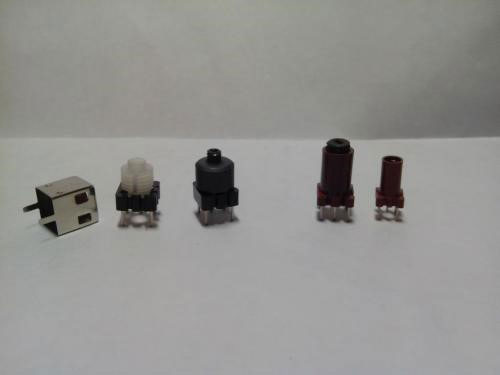
Trimmer inductance
In some cases, it is required to accurately set the value of the inductance on site after connecting the coil to other circuit elements, compensating for parameter deviations during tuning. For this, different methods are used (switching the taps of the turns, etc.), but the most accurate and smooth method is tuning with the help of a core. It is made in the form of a threaded rod, which can be screwed in and out inside the frame, adjusting the inductance of the coil.
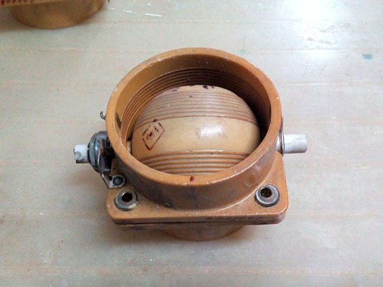
Variable inductance (variometer)
Where an on-line adjustment of inductance or inductive coupling is required, coils of a different design are used. They contain two windings - movable and fixed. The total inductance is equal to the sum of the inductances of the two coils and the mutual inductance between them.
By changing the relative position of one coil to another, the total value of the inductance is adjusted. Such a device is called a variometer and is often used in communications equipment to tune resonant circuits in cases where the use of variable capacitors is impossible for some reason.The design of the variometer is rather bulky, which limits its scope.
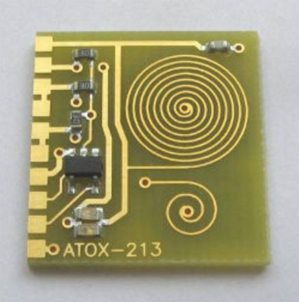
Inductance in the form of a printed spiral
Coils with a small inductance can be made in the form of a spiral of printed conductors. The advantage of this design are:
- manufacturability of production;
- high repeatability of parameters.
The disadvantages include the impossibility of fine tuning during adjustment and the difficulty of obtaining large inductance values - the higher the inductance, the more space the coil takes up on the board.
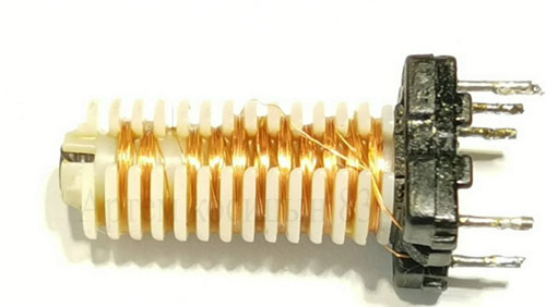
Sectional wound reel
Inductance without capacitance is only on paper. With any physical implementation of the coil, a parasitic interturn capacitance immediately arises. This is harmful in many cases. The parasitic capacitance adds up to the capacitance of the LC circuit, reducing the resonant frequency and the quality factor of the oscillatory system. Also, the coil has its own resonant frequency, which provokes undesirable phenomena.
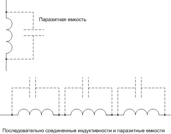
Various methods are used to reduce parasitic capacitance, the simplest of which is winding inductance in the form of several series-connected sections. With this inclusion, the inductances add up, and the total capacitance decreases.
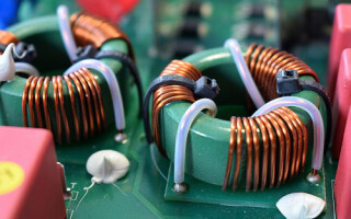
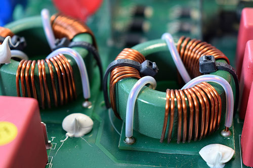
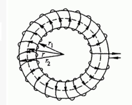
Inductor on a toroidal core
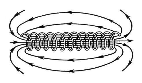
The magnetic field lines of a cylindrical inductor are drawn through the inside of the winding (if there is a core, then through it) and closed from the outside through the air. This fact entails several disadvantages:
- the inductance is reduced;
- the characteristics of the coil are less amenable to calculation;
- any object brought into an external magnetic field changes the parameters of the coil (inductance, parasitic capacitance, losses, etc.), so shielding is required in many cases.
Coils wound on toroidal cores (in the form of a ring or a donut) are largely free from these shortcomings. Magnetic lines pass inside the core in the form of closed loops. This means that external objects have practically no effect on the parameters of a coil wound on such a core, and shielding is not needed for such a design. The inductance also increases, other things being equal, and the characteristics are easier to calculate.
The disadvantages of coils wound on tori include the impossibility of smooth adjustment of the inductance on the spot. Another problem is the high labor intensity and low manufacturability of winding. However, this applies to all inductive elements in general, to a greater or lesser extent.
Also, a common disadvantage of the physical implementation of the inductance is high weight and size, relatively low reliability and low maintainability.
Therefore, in technology, they try to get rid of inductive components. But this is not always possible, so winding components will be used both in the foreseeable future and in the medium term.
Similar articles: