A thermocouple is a device for measuring temperatures in all branches of science and technology. This article presents a general overview of thermocouples with an analysis of the design and principle of operation of the device. Varieties of thermocouples with their brief characteristics are described, and an assessment of the thermocouple as a measuring instrument is also given.
Content
Thermocouple device
The principle of operation of a thermocouple. Seebeck effect
The operation of a thermocouple is due to the occurrence of the thermoelectric effect, discovered by the German physicist Tomas Seebeck in 1821.
The phenomenon is based on the occurrence of electricity in a closed electrical circuit when exposed to a certain ambient temperature. An electric current occurs when there is a temperature difference between two conductors (thermoelectrodes) of different composition (dissimilar metals or alloys) and is maintained by maintaining the place of their contacts (junctions). The device displays the value of the measured temperature on the screen of the connected secondary device.
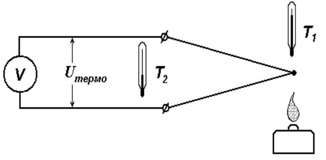
The output voltage and temperature are linearly related. This means that an increase in the measured temperature results in a higher millivolt value at the free ends of the thermocouple.
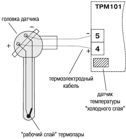
The junction located at the point of temperature measurement is called “hot”, and the place where the wires are connected to the converter is called “cold”.
Cold junction temperature compensation (CJC)
Cold junction compensation (CJC) is a compensation applied as a correction to the total reading when measuring the temperature at the point where the thermocouple leads are connected. This is due to discrepancies between the actual temperature of the cold ends and the calculated readings of the calibration table for the temperature of the cold junction at 0°C.
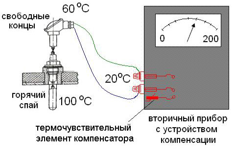
CCS is a differential method in which absolute temperature readings are found from a known cold junction temperature (also known as a reference junction).
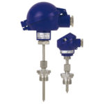
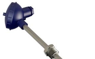
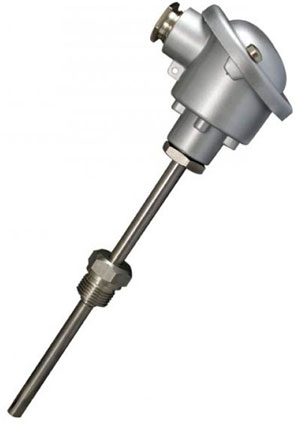
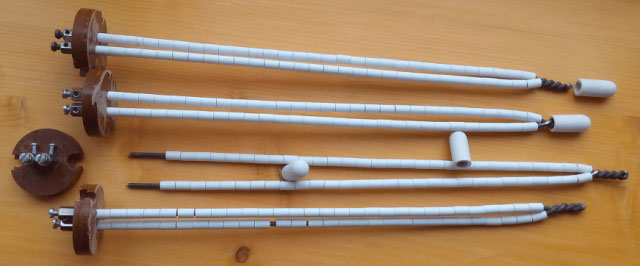
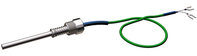
Thermocouple design
When designing a thermocouple, the influence of such factors as the "aggressiveness" of the external environment, the state of aggregation of the substance, the range of measured temperatures, and others are taken into account.
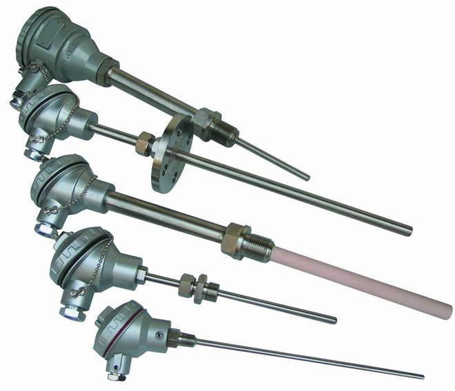
Thermocouple design features:
1) Junctions of conductors are interconnected by twisting or twisting with further electric arc welding (rarely by soldering).
IMPORTANT: It is not recommended to use the twisting method due to the rapid loss of junction properties.
2) Thermoelectrodes must be electrically isolated along their entire length, except for the point of contact.
3) The insulation method is selected taking into account the upper temperature limit.
- Up to 100-120°C - any insulation;
- Up to 1300°C - porcelain tubes or beads;
- Up to 1950°C - Al tubes2O3;
- Above 2000°С - tubes made of MgO, BeO, ThO2, ZrO2.
4) Protective cover.
The material must be thermally and chemically resistant, with good thermal conductivity (metal, ceramics). The use of a boot prevents corrosion in certain environments.
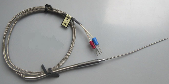
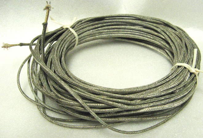
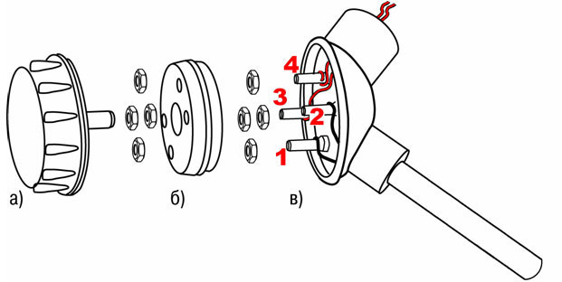
Extension (compensation) wires
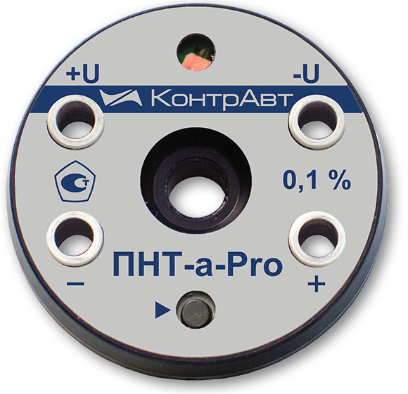
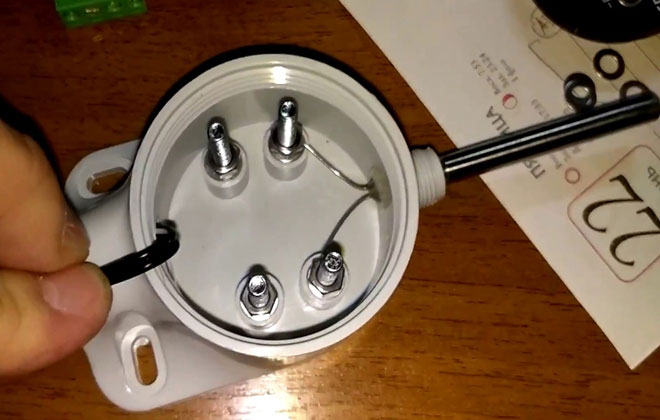
This type of wire is needed to extend the ends of the thermocouple to the secondary device or barrier. Wires are not used if the thermocouple has a built-in converter with a unified output signal. The most widely used is the normalizing converter, located in the standard terminal head of the sensor with a unified signal 4-20mA, the so-called "tablet".
The material of the wires may coincide with the material of thermoelectrodes, but most often it is replaced with a cheaper one, taking into account the conditions that prevent the formation of parasitic (induced) thermo-emfs. The use of extension wires also allows you to optimize production.
Life hack! To correctly determine the polarity of the compensating wires and connect them to the thermocouple, remember the mnemonic rule MM - minus is magnetized. That is, we take any magnet and the minus of the compensation will be magnetized, unlike the plus.
Types and types of thermocouples
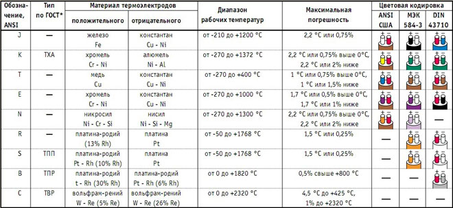
The variety of thermocouples is explained by various combinations of metal alloys used. The choice of thermocouple is carried out depending on the industry and the required temperature range.
Thermocouple chromel-alumel (TXA)
Positive electrode: chromel alloy (90% Ni, 10% Cr).
Negative electrode: alumel alloy (95% Ni, 2% Mn, 2% Al, 1% Si).
Insulation material: porcelain, quartz, metal oxides, etc.
Temperature range from -200°С to 1300°С short-term and 1100°С long-term heating.
Working environment: inert, oxidizing (O2=2-3% or completely excluded), dry hydrogen, short-term vacuum. In a reducing or redox atmosphere in the presence of a protective cover.
Disadvantages: ease of deformation, reversible instability of thermo-EMF.
There may be cases of corrosion and embrittlement of alumel in the presence of traces of sulfur in the atmosphere and chromel in a weakly oxidizing atmosphere (“green clay”).
Thermocouple chromel-kopel (TKhK)
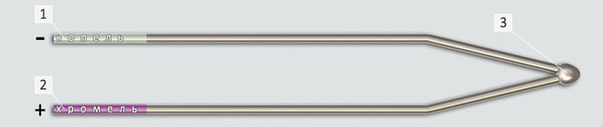
Positive electrode: chromel alloy (90% Ni, 10% Cr).
Negative electrode: Kopel alloy (54.5% Cu, 43% Ni, 2% Fe, 0.5% Mn).
Temperature range from -253°С to 800°С long-term and 1100°С short-term heating.
Working environment: inert and oxidizing, short-term vacuum.
Disadvantages: thermoelectrode deformation.
Possibility of chromium evaporation under prolonged vacuum; reaction with an atmosphere containing sulfur, chromium, fluorine.
Thermocouple iron-constantan (TGK)
Positive electrode: commercially pure iron (mild steel).
Negative electrode: constantan alloy (59% Cu, 39-41% Ni, 1-2% Mn).
Used for measurements in reducing, inert media and vacuum. Temperature from -203°С to 750°С long-term and 1100°С short-term heating.
Application develops on joint measurement of positive and negative temperatures. It is unprofitable to use only for negative temperatures.
Disadvantages: thermoelectrode deformation, low corrosion resistance.
Changes in the physicochemical properties of iron at about 700°C and 900°C. Reacts with sulfur and water vapor to form corrosion.
Tungsten-rhenium thermocouple (TVR)
Positive electrode: alloys BP5 (95% W, 5% Rh) / BAP5 (BP5 with silica and aluminum additive) / BP10 (90% W, 10% Rh).
Negative electrode: BP20 alloys (80% W, 20% Rh).
Insulation: chemically pure metal oxide ceramics.
Mechanical strength, heat resistance, low sensitivity to pollution, ease of manufacture are noted.
Measurement of temperatures from 1800°С to 3000°С, the lower limit is 1300°С. Measurements are carried out in an inert gas, dry hydrogen or vacuum environment. In oxidizing environments only for measurement in fast processes.
Disadvantages: poor reproducibility of thermo-EMF, its instability during irradiation, unstable sensitivity in the temperature range.
Thermocouple tungsten-molybdenum (VM)
Positive electrode: tungsten (commercially pure).
Negative electrode: molybdenum (commercially pure).
Insulation: alumina ceramic, protected with quartz tips.
Inert, hydrogen or vacuum environment. It is possible to carry out short-term measurements in oxidizing environments in the presence of insulation.The range of measured temperatures is 1400-1800°C, the maximum operating temperature is about 2400°C.
Disadvantages: poor reproducibility and sensitivity of thermal EMF, polarity reversal, embrittlement at high temperatures.
Thermocouples platinum-rhodium-platinum (TPP)
Positive electrode: platinum-rhodium (Pt c 10% or 13% Rh).
Negative electrode: platinum.
Insulation: quartz, porcelain (plain and refractory). Up to 1400°C - ceramics with a high content of Al2O3, over 1400°C - ceramics from chemically pure Al2O3.
Maximum operating temperature 1400°C long-term, 1600°C short-term. Measurement of low temperatures is usually not performed.
Working environment: oxidizing and inert, reducing in the presence of protection.
Disadvantages: high cost, instability during irradiation, high sensitivity to contamination (especially the platinum electrode), metal grain growth at high temperatures.
Thermocouples platinum-rhodium-platinum-rhodium (TPR)
Positive electrode: Pt alloy with 30% Rh.
Negative electrode: Pt alloy with 6% Rh.
Medium: oxidizing, neutral and vacuum. Use in reducing and containing vapors of metals or non-metals in the presence of protection.
Maximum operating temperature 1600°C long-term, 1800°C short-term.
Insulation: Al ceramic2O3 high purity.
Less susceptible to chemical contamination and grain growth than a platinum-rhodium-platinum thermocouple.
Thermocouple wiring diagram
- Connecting a potentiometer or galvanometer directly to the conductors.
- Connection with compensating wires;
- Connection with conventional copper wires to a thermocouple with a unified output.
Thermocouple Conductor Color Standards
Colored conductor insulation helps to distinguish thermoelectrodes from each other for proper connection to the terminals. Standards differ by country, there are no specific color codes for conductors.
IMPORTANT: It is necessary to know the standard used in the enterprise to prevent errors.
Measurement accuracy
Accuracy depends on thermocouple type, temperature range, purity of material, electrical noise, corrosion, junction properties, and manufacturing process.
Thermocouples are assigned a tolerance class (standard or special) that establishes a measurement confidence interval.
IMPORTANT: Characteristics at the time of manufacture change during operation.
Measurement speed
The speed is determined by the ability of the primary converter to quickly respond to temperature jumps and the flow of input signals of the measuring device that follows them.
Factors that increase performance:
- Correct installation and calculation of the length of the primary converter;
- When using a transducer with a protective sleeve, it is necessary to reduce the mass of the unit by selecting a smaller diameter of the sleeves;
- Minimizing the air gap between the primary converter and the protective sleeve;
- The use of a spring-loaded primary converter and filling the voids in the sleeve with a heat-conducting filler;
- A fast moving or denser medium (liquid).
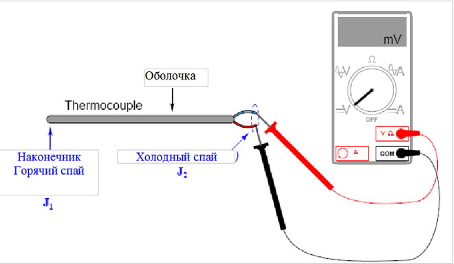
Thermocouple Performance Check
To check the performance, connect a special measuring device (tester, galvanometer or potentiometer) or measure the output voltage with a millivoltmeter. If there are fluctuations of the arrow or digital indicator, the thermocouple is serviceable, otherwise the device must be replaced.
Causes of thermocouple failure:
- Failure to use a protective shielding device;
- Change in the chemical composition of the electrodes;
- Oxidative processes developing at high temperatures;
- Breakdown of the control and measuring device, etc.
Advantages and disadvantages of using thermocouples
The advantages of using this device are:
- Large temperature measurement range;
- High accuracy;
- Simplicity and reliability.
The disadvantages include:
- Implementation of continuous monitoring of the cold junction, verification and calibration of control equipment;
- Structural changes in metals during the manufacture of the device;
- Dependence on the composition of the atmosphere, the cost of sealing;
- Measurement error due to electromagnetic waves.