Electromagnetic static devices are used to generate and apply a magnetic field. There are many cases why a transformer is needed in electronic, electrical circuits and radio engineering. The device is equipped with inductive windings interconnected on a magnetic core. The network contributes to the emergence of an alternating field, and the transformer, using electromagnetic induction, gives the current constant values \u200b\u200bwithout changing the frequency.
Content
Definition and purpose
To power devices, voltages of various characteristics are needed. A transformer is a design for using the inductive work of a magnetic field. Tape or wire coils, united by a common flux, lower or increase the voltage. The TV uses 5 V to operate transistors and microcircuits, the kinescope power requires several kilovolts when using a cascade generator.
Insulated windings are located on a core made of spontaneously magnetized material with a certain tension value. Older units used the existing mains frequency, around 60 Hz. In modern power supply circuits for electrical appliances, pulse transformers with a high frequency are used. Alternating voltage is rectified and converted by means of a generator into a value with specified parameters.
The voltage is stabilized by a PWM control unit. High-frequency bursts are transmitted to the transformer, stable performance is obtained at the output. The massiveness and heaviness of the instruments of past years is replaced by lightness and small size. The linear indicators of the unit are proportional to the power in a ratio of 1: 4; to reduce the dimensions of the device, the frequency of the current increases.
Massive devices are used in power supply circuits if it is required to create a minimum level of high-frequency interference dispersion, for example, when providing high-quality sound.
Device and principle of operation
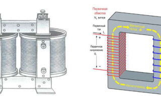
The manufacturer chooses the basic rules for the operation of the unit, but this does not affect the reliability of operation. The concepts differ in the manufacturing process. The principle of operation of the transformer is based on two provisions:
- the changing motion of directional charge carriers creates an alternating magnetic force field;
- influence on the power flow transmitted through the coil produces electromotive force and induction.
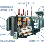
The device consists of the following parts:
- magnetic circuit (core);
- coil or winding;
- basis for the location of the turns;
- insulating material;
- cooling system;
- other elements of fastening, access, protection.
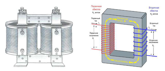
The work of the transformer is carried out according to the type of design and combination of the core and windings.In the rod type, the conductor is enclosed in windings, it is difficult to see it. The coils of the spiral are visible, the top and bottom of the core are visible, the axis is vertical. The material of which the coil consists must conduct electricity well.
In armored products, the rod hides most of the turns; it is placed horizontally or vertically. The toroidal design of transformers provides for the location of two independent windings on the magnetic circuit without electrical connection between them.
Magnetic system
It is made of alloyed transformer steel, ferrite, permalloy while maintaining the geometric shape to produce the magnetic field of the unit. The conductor is constructed from plates, ribbons, horseshoes, it is made on a press. The part on which the winding is located is called the rod. A yoke is an element without turns that completes the circuit.
The principle of operation of the transformer depends on the layout of the racks, which happens:
- flat - the axes of the yokes and cores are in the same plane;
- spatial - longitudinal elements are arranged in different surfaces;
- symmetrical - conductors of the same shape, size and design are located to all yokes similarly to others;
- asymmetrical - individual racks differ in appearance, dimensions and are placed in different positions.
If it is assumed that a direct current flows through the winding, which is called the primary, then the magnetic wire is made open. In other cases, the core is closed; it serves to close the power lines.
windings
They are made in the form of a set of turns arranged on square conductors.The shape is used to work efficiently and increase the fill factor in the magnetic circuit window. If it is required to increase the cross section of the core, then it is made in the form of two parallel elements in order to reduce the occurrence of eddy currents. Each such conductor is called residential.
The rod is wrapped in paper, covered with enamel varnish. Sometimes two cores arranged in parallel are enclosed in a common insulation, the set is called a cable. Windings are distinguished by purpose:
- the main ones - an alternating current is supplied to them, a converted electric current comes out;
- regulating - they provide taps for voltage transformation at a low current strength;
- auxiliary - serve to supply their network with a power less than the nominal value of the transformer and bias the circuit with direct current.
Wrapping methods:
- ordinary winding - turns are made in the direction of the axis along the entire length of the conductor, subsequent turns are wound tightly, without gaps;
- screw winding - multi-layer wrapping with gaps between the rings or approaching adjacent elements;
- disk winding - a spiral row is performed sequentially, in a circle, wrapping is performed in a radial order in the inner and outer directions;
- the foil spiral is placed from an aluminum and copper wide sheet, the thickness of which varies between 0.1-2 mm.
Conventions
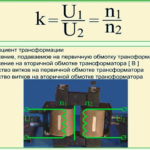
To make it easy to read the transformer diagram, there are special signs. The core is drawn with a thick line, the number 1 shows the primary winding, the secondary turns are indicated by the numbers 2 and 3.
In some schemes, the core line is similar in thickness to the line of the wrapping semicircles. The designation of the rod material is different:
- a ferrite magnetic circuit is drawn with a thick line;
- a steel core with a magnetic gap is drawn with a thin line with a gap in the middle;
- the axis of the magnetized dielectric is indicated by a thin dotted line;
- the copper rod has the appearance of a narrow line in the diagram with the symbol of the material according to the periodic table.
Bold dots are used to highlight the coil output, the designation of instantaneous induction is the same. Used to indicate intermediate units in cascaded generators to indicate antiphase. Put dots if you want to set the polarity during assembly and the direction of the windings. The number of turns in the primary winding is determined conditionally, just as the number of semicircles is not standardized, there is proportionality, but it is not strictly observed.
Main characteristics
Idle mode is used when the secondary circuit of the transformer is open, there is no voltage in it. The current passes through the primary winding, reactive magnetization occurs. With the help of idle work, the efficiency, the transformation rate and the loss in the core are determined.
Operation under load means connecting the power source to the primary circuit, where the total current of operation and idling flows. The load is connected to the secondary circuit of the transformer. This mode is common.
The short circuit phase occurs if the resistance of the secondary coil is the only load. In this mode, the heating losses of the coil in the circuit are determined.Transformer parameters are taken into account in the device substitution system by setting the resistance.
The ratio of consumed and output power determines the efficiency of the transformer.
Application area
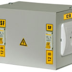
Household appliances have contact with earth through a neutral wire. Simultaneous contact by the current consumer of the phase and the zero circuit leads to circuit closure and injury. Connection through an isolating transformer allows you to protect a person, since the secondary winding does not come into contact with the ground.
Pulse units are used in the transmission of a rectangular push and the transformation of short signals under load. At the output, the polarity and amplitude of the current changes, but the voltage remains unchanged.
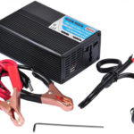
DC measuring equipment is a magnetic amplifier. The directional movement of low power electrons helps to change the alternating voltage. The rectifier supplies constant energy and depends on the input electricity values.
Power units are widely used in small current generators, power, indicators in diesel engines are average. Transformers are mounted in series with the load, the device is connected to the source by the primary winding, the secondary circuit produces the converted energy. The value of the output current is directly proportional to the load. Equipment with 3 magnetic bars is used if the generator is three-phase current.
Inverting units have transistors of the same conductivity and amplify only part of the signal at the output. For complete voltage conversion, a pulse is applied to both transistors.
Matching equipment is used to connect to electronic devices with high resistance at the input and output of the load with a low rate of electricity transmission. The units are useful in high frequency lines where the difference in magnitude leads to energy losses.
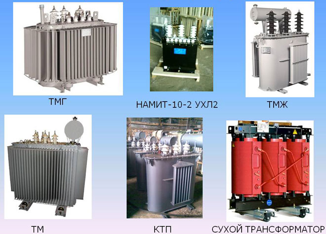
Types of transformers
The classification of transformers depends on the rated value of the current in the primary and secondary circuits. In common species, the indicator is in the range of 1-5 A.
The separating unit does not provide for the connection of both spirals. The equipment provides galvanic isolation, i.e. the transmission of an impulse in a non-contact way. Without it, the current flowing between the circuits is limited only by the resistance, which is not taken into account due to the small value.
The matching transformer ensures that the different resistance values are matched to minimize output waveform distortion. Serves for the organization of galvanic isolation.
Before finding out what power transformers are, they note that they are produced to work with high power networks. Alternating current devices change the energy performance in receiving installations and work in places with a large capacity and rate of change of electricity.
A rotary transformer should not be confused with rotating equipment, a machine for converting the angle of rotation into circuit voltage, where the efficiency depends on the rotational speed. The device transmits an electrical impulse to the moving parts of the equipment, for example, to the head of a VCR. Double core with separate windings, one of which turns around the other.
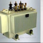
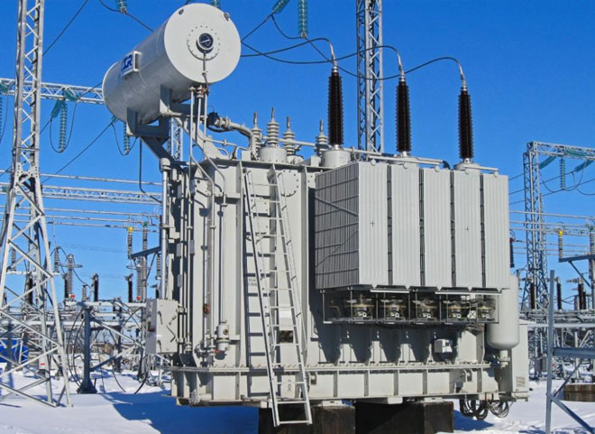
The oil unit uses coil cooling with special transformer oil.They have a closed circuit. Unlike air species, they can interact with high power networks.
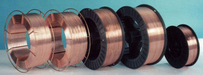
Welding transformers for optimizing equipment performance, reducing voltage and generating high frequency current. This is due to a change in inductive reactance or idle performance. Step regulation is carried out by the layout of the electrical winding on the conductors.