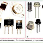
Field (unipolar) a transistor is a device that has three outputs and is controlled by applied to the control electrode (shutter) voltage. Regulated current flows through the source-drain circuit.
The idea of such a triode arose about 100 years ago, but it became possible to approach practical implementation only in the middle of the last century. In the 50s of the last century, the concept of a field-effect transistor was developed, and in 1960 the first working sample was manufactured. To understand the advantages and disadvantages of triodes of this type, you need to understand their design.
Content
FET device
Unipolar transistors are divided into two large classes according to the device and manufacturing technology. Despite the similarity of control principles, they have design features that determine their characteristics.
Unipolar triodes with p-n junction
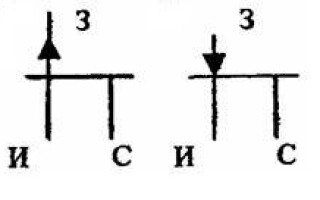
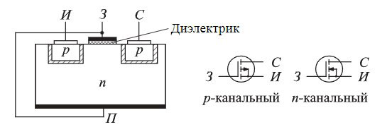
The device of such a field worker is similar to the device of a conventional semiconductor diode and, unlike the bipolar relative, contains only one transition. A p-n junction transistor consists of a plate of one type of conductor (for example, n), and an embedded region of another type of semiconductor (in this case, p).
The N-layer forms a channel through which current flows between the source and drain terminals. The gate pin is connected to the p-region. If a voltage is applied to the gate that biases the transition in the opposite direction, then the transition zone expands, the channel cross section, on the contrary, narrows, and its resistance increases. By controlling the gate voltage, the current in the channel can be controlled. Transistor can also be performed with a p-type channel, then the gate is formed by an n-semiconductor.
One of the features of this design is the very large input resistance of the transistor. The gate current is determined by the resistance of the reverse-biased junction, and is at a constant current of units or tens of nanoamperes. On alternating current, the input resistance is set by the junction capacitance.
Gain stages assembled on such transistors, due to the high input resistance, simplify matching with input devices. In addition, during the operation of unipolar triodes, there is no recombination of charge carriers, and this leads to a decrease in low-frequency noise.
In the absence of a bias voltage, the channel width is greatest, and the current through the channel is maximum. By increasing the voltage, it is possible to achieve such a state of the channel when it is completely blocked. This voltage is called the cutoff voltage (Uts).
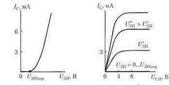
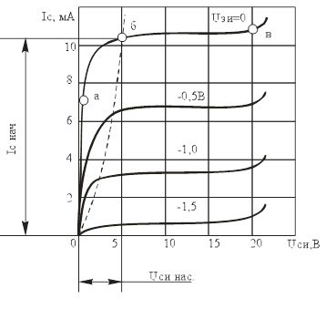 The drain current of a FET depends on both the gate-to-source voltage and the drain-to-source voltage. If the voltage at the gate is fixed, with an increase in Us, the current first grows almost linearly (section ab). When entering saturation, a further increase in voltage practically does not cause an increase in the drain current (section bc). With an increase in the blocking voltage level at the gate, saturation occurs at lower values of Idock.
The figure shows a family of drain current vs. voltage between source and drain for several gate voltages. It is obvious that when Us is higher than the saturation voltage, the drain current depends practically only on the gate voltage.
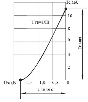 This is illustrated by the transfer characteristic of a unipolar transistor. As the negative value of the gate voltage increases, the drain current drops almost linearly down to zero when the cutoff voltage level is reached at the gate.
Unipolar insulated gate triodes
Another version of the field effect transistor is with an insulated gate. Such triodes are called transistors. TIR (metal-dielectric-semiconductor), foreign designation - MOSFET. Previously the name was taken MOS (metal-oxide-semiconductor).
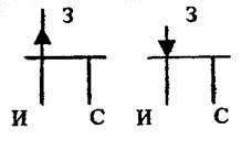
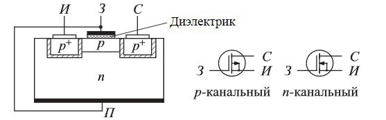 The substrate is made of a conductor of a certain type of conductivity (in this case, n), the channel is formed by a semiconductor of a different type of conductivity (in this case, p). The gate is separated from the substrate by a thin layer of dielectric (oxide), and can affect the channel only through the generated electric field.At a negative gate voltage, the generated field displaces electrons from the channel region, the layer becomes depleted, and its resistance increases. For p-channel transistors, on the contrary, the application of a positive voltage leads to an increase in resistance and a decrease in current.
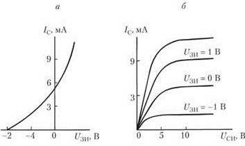 Another feature of the insulated gate transistor is the positive portion of the transfer characteristic (negative for a p-channel triode). This means that a certain amount of positive polarity voltage can be applied to the gate, which will increase the drain current. The family of output characteristics has no fundamental differences from the characteristics of a triode with a p-n junction.
The dielectric layer between the gate and the substrate is very thin, so MOS transistors from early years of production (for example, domestic KP350) were extremely sensitive to static electricity. The high voltage pierced the thin film, destroying the transistor. In modern triodes, design measures are taken to protect against overvoltage, so static precautions are practically not needed.
 Another version of the unipolar insulated gate triode is the induced channel transistor. It does not have a built-in channel; in the absence of voltage at the gate, the current from the source to the drain will not flow. If a positive voltage is applied to the gate, then the field created by it “pulls” electrons from the n-zone of the substrate, and creates a channel for current flow in the near-surface region.From this it is clear that such a transistor, depending on the type of channel, is controlled by a voltage of only one polarity. This can be seen from its passage characteristics.
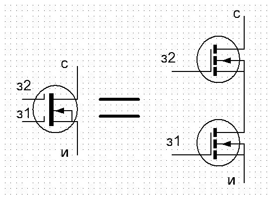
There are also bi-gate transistors. They differ from the usual ones in that they have two equal gates, each of which can be controlled by a separate signal, but their effect on the channel is summed up. Such a triode can be represented as two ordinary transistors connected in series.
FET switching circuits
The scope of field effect transistors is the same as that of bipolar. They are mainly used as reinforcing elements. Bipolar triodes, when used in amplifying stages, have three main switching circuits:
- with a common collector (emitter follower);
- with a common base;
- with a common emitter.
Field effect transistors are switched on in similar ways.
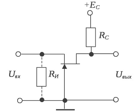
Scheme with a common drain
Scheme with a common drain (source follower), just like the emitter follower on a bipolar triode, does not provide voltage gain, but assumes current gain.
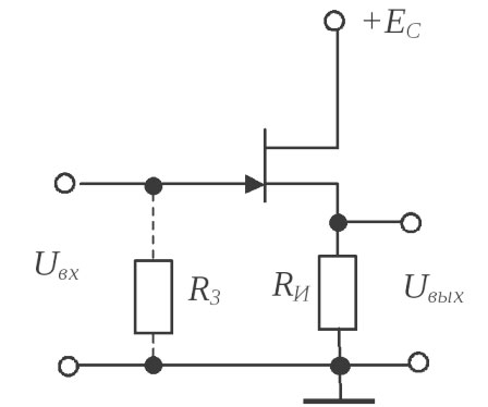
The advantage of the circuit is the high input impedance, but in some cases it is also a disadvantage - the cascade becomes sensitive to electromagnetic interference. If necessary, Rin can be reduced by turning on the resistor R3.
Common gate circuit
This circuit is similar to that of a common base bipolar transistor. This circuit gives good voltage gain, but no current gain. Like the inclusion with a common base, this option is used infrequently.
Common source circuit
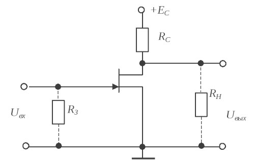 The most common circuit for switching on field triodes with a common source.Its gain depends on the ratio of the resistance Rc to the resistance in the drain circuit (an additional resistor can be installed in the drain circuit to adjust the gain), and also depends on the steepness of the characteristics of the transistor.
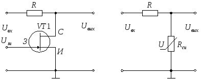
Also, field-effect transistors are used as a controlled resistance. To do this, the operating point is selected within the linear section. According to this principle, a controlled voltage divider can be implemented.
And on a double-gate triode in this mode, you can implement, for example, a mixer for receiving equipment - the received signal is fed to one gate, and to the other - local oscillator signal.
If we accept the theory that history develops in a spiral, we can see a pattern in the development of electronics. Moving away from voltage-controlled lamps, technology has moved on to bipolar transistors, which require current to control. The spiral has made a full turn - now there is a dominance of unipolar triodes, which, like lamps, do not require power consumption in control circuits. It will be seen where the cyclic curve will lead further. So far, there is no alternative to field-effect transistors.
Similar articles: