In radio electronics and microcircuitry, the operational amplifier (op-amp) is widely used. It has excellent technical characteristics (TX) for signal amplification. To understand the scope of the OS, you need to know its principle of operation, the connection diagram and the main TX.
Content
What is an operational amplifier
OU - an integrated circuit (IC), the main purpose of which is to amplify the value of direct current. It has only one output, which is called differential. This output has a high signal amplification factor (Ky). Op-amps are mainly used in the construction of circuits with negative feedback (NFB), which, with the main gain TX, determines Ku of the original circuit. Op-amps are used not only in the form of individual ICs, but also in different blocks of complex devices.
The op-amp has 2 inputs and 1 output, and also has leads for connecting a power source (IP). The principle of operation of an operational amplifier is simple. There are 2 rules taken as a basis.The rules describe the simple processes of the IC operation that take place in the OS, and how the IC works is clear even to dummies. At the output, the voltage difference (U) is 0, and the op-amp inputs draw almost no current (I). One input is called non-inverting (V+) and the other is called inverting (V-). In addition, the op-amp inputs have a high resistance (R) and consume almost no I.
The chip compares the U values at the inputs and outputs a signal after amplifying it. Ku OU has a high value, reaching 1000000. If a low U is applied to the input, then at the output it is possible to obtain a value equal to U of the power source (Uip). If U at the input V+ is greater than at V-, then the output will be the maximum positive value. When powered by a positive U of the inverting input, the output will have a maximum negative voltage.
The main requirement for the operation of the OS is the use of a bipolar IP. It is possible to use a unipolar IP, but the capabilities of the op-amp are severely limited. If you use a battery and take its plus side as 0, then when measuring the values, you get 1.5 V. If you take 2 batteries and connect them in series, then U will be added, i.e. the device will show 3 V.
If we take the negative terminal of the battery as zero, then the device will show 3 V. Otherwise, if we take the positive terminal as 0, then we get -3 V. When using the point between the two batteries as zero, we get a primitive bipolar IP. You can check the health of the op-amp only when you connect it to the circuit.
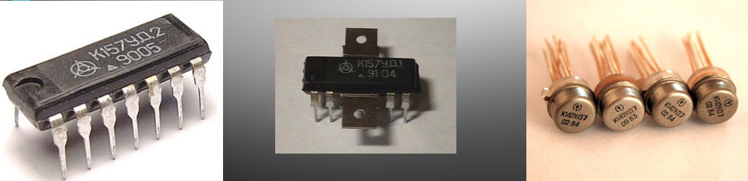
Types and symbols on the diagram
With the development of electrical circuitry, operational amplifiers are constantly being improved and new models appear.
Classification by application:
- Industrial is a cheap option.
- Precision (precise measuring equipment).
- Electrometric (small value of Iin).
- Micropower (consumption of small I power).
- Programmable (currents are set using I external).
- Powerful or high-current (giving a larger value of I to the consumer).
- Low-voltage (operate at U<3 V).
- High voltage (designed for high U values).
- Fast response (high slew rate and gain frequency).
- With low noise level.
- Sonic type (low harmonics).
- For bipolar and unipolar type of electrical supply.
- Difference (capable of measuring low U at high noise). Used in shunts.
- Amplifying cascades of the finished type.
- Specialized.
According to the input signals, the op amps are divided into 2 types:
- With 2 entrances.
- With 3 inputs. 3 input is used to expand functionality. Has an internal OOS.
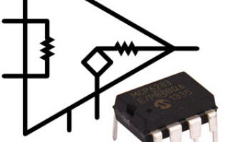
The operational amplifier circuit is quite complicated, and it makes no sense to manufacture it, and the radio amateur only needs to know the correct operational amplifier switching circuit, but for this one should understand the decoding of its conclusions.
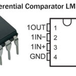
The main designations of the findings of the IC:
- V+ is a non-inverting input.
- V- - inverting input.
- Vout - output. Vs + (Vdd, Vcc, Vcc +) - positive terminal of the IP.
- Vs- (Vss, Vee, Vcc-) - minus IP.
In almost any op-amp there are 5 conclusions. However, some varieties may lack the V-. There are models that have additional conclusions that expand the capabilities of the op-amp.
Conclusions for power supply do not have to be marked, because. this increases the readability of the diagram. The power output from the positive terminal or pole of the IP is located at the top of the circuit.
Main characteristics
Op-amps, like other radio components, have TX, which can be divided into types:
- Amplifying.
- Input.
- Weekends.
- Energy.
- Drift.
- Frequency.
- performance.
The gain is the main characteristic of the op amp. It is characterized by the ratio of the output signal to the input. It is also called amplitude, or transfer TX, which is presented in the form of dependency graphs. The input includes all values for the input of the op-amp: Rin, bias currents (Ism) and shift (Iin), drift and maximum input differential U (Udifmax).
Icm is used to operate the op-amp at the inputs. Iin is needed for the operation of the input stage of the op-amp. Iin shift - the difference Icm for 2 input semiconductors of the op-amp.
During the construction of circuits, these I must be taken into account when connecting resistors. If Iin is not taken into account, then this can lead to the creation of a differential U, which will lead to incorrect operation of the op-amp.
Udifmax - U, which is fed between the inputs of the op-amp. Its value characterizes the exclusion of damage to the semiconductors of the differential cascade.
For reliable protection between the inputs of the op-amp, 2 diodes and a zener diode are connected in anti-parallel. The differential input R is characterized by the R between the two inputs, and the common mode input R is the value between the 2 inputs of the op amp that are combined and ground (ground). The output parameters of the op amp include output R (Rout), maximum output U, and I. The Rout parameter should be smaller in value for better gain characteristics.
To achieve a small Rout, you need to use an emitter follower. Iout is changed with the collector I.Energy TX are estimated by the maximum power that the OS consumes. The reason for the incorrect operation of the op-amp is the spread of the TX of the semiconductors of the differential amplifier stage, which depends on temperature indicators (temperature drift). The frequency parameters of the op-amp are the main ones. They contribute to the amplification of harmonic and impulse signals (speed).
In the IC op-amp of a general and special form, a capacitor is included to prevent the generation of high-frequency signals. At frequencies with a low value, the circuits have a large K coefficient without feedback (OS). The OS uses a non-inverting connection. In addition, in some cases, for example, in the manufacture of an inverting amplifier, the OS is not used. In addition, the op-amp has dynamic characteristics:
- Slew rate Uout (SN Uout).
- Settling time Uout (op-amp response at jump U).
Where applicable
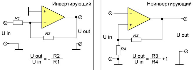
There are 2 types of op-amp circuits, which differ in the way they are connected. The main drawback of the OU is the inconsistency of Ku, which depends on the mode of operation. The main areas of application are amplifiers: inverting (IU) and non-inverting (NIO). In the NRU circuit, Ku by U is set by resistors (the signal must be applied to the input). The OU contains an OOS of a sequential type. This connection is made on one of the resistors. It is served only on V-.
In the DUT, the signals are phase shifted. To change the sign of the output negative voltage, a parallel feedback on U is needed. The input, which is non-inverting, must be grounded. The input signal is fed through a resistor to the inverting input.If the non-inverting input goes to ground, then the difference U between the inputs of the op amp is 0.
You can select devices that use OS:
- Preamplifiers.
- Amplifiers of audio and video frequency signals.
- U comparators.
- Diffamplifiers.
- Differentiators.
- Integrators.
- filter elements.
- Rectifiers (increased accuracy of output parameters).
- Stabilizers U and I.
- Calculator analog type.
- ADC (analogue-to-digital converters).
- DAC (digital-to-analog converters).
- Devices for generating various signals.
- Computer technology.
Operational amplifiers and their application are widely used in various equipment.
Similar articles: