Almost all electrical circuits include capacitive elements. The connection of capacitors to each other is performed according to the schemes. They need to be known both during calculations and during installation.
serial connection
Capacitor, and colloquially - "capacity", that part, without which not a single electrical or electronic board can do. Even in modern gadgets, it is present, however, already in a modified form.
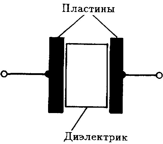
Let's remember what this radio element is. This is a storage of electric charges and energy, 2 conductive plates, between which there is a dielectric. When a direct current source is applied to the plates, a current will flow briefly through the device, and it will charge up to the source voltage. Its capacity is used to solve technical problems.
The word itself came about long before the device was invented.The term appeared even when people believed that electricity is something like a liquid, and you can fill a vessel with it. With regard to the capacitor - it is unsuccessful, because. implies that the appliance can only hold a finite amount of electricity. Although this is not the case, the term has remained unchanged.
The larger the plates, and the smaller the distance between them, the greater the capacitance of the capacitor. If its plates are connected to any conductor, then a rapid discharge will occur through this conductor.
In coordinate telephone exchanges, with the help of this feature, signals are exchanged between devices. The length of the pulses required for commands, such as: “line connection”, “subscriber answer”, “hang up”, is regulated by the capacitance value of the capacitors installed in the circuit.
The unit of capacitance is 1 Farad. Because this is a large value, then they use microfarads, picofarads and nanofarads, (μF, pF, nF).
In practice, by making a series connection, it is possible to achieve an increase in the applied voltage. In this case, the applied voltage is received by 2 outer plates of the assembled system, and the plates inside are charged using charge distribution. Such methods are resorted to when the necessary elements are not at hand, but there are details of other voltage ratings.
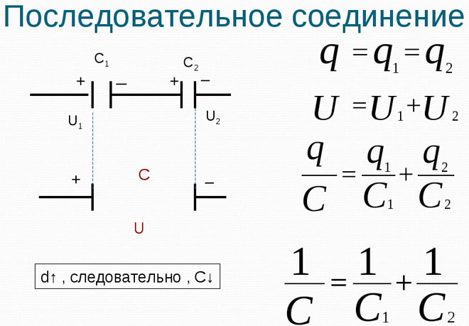
A section with 2 125 V capacitors connected in series can be connected to a 250 V power supply.
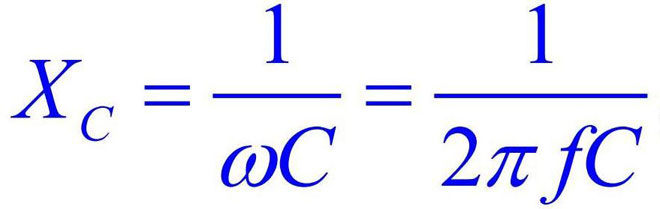
If for direct current, the capacitor is an obstacle due to its dielectric gap, then with a variable, everything is different.For currents of different frequencies, like coils and resistors, the resistance of a capacitor will vary. It passes high-frequency currents well, and creates a barrier for their low-frequency counterparts.
Radio amateurs have a way - through a capacitance of 220-500 pF, instead of an antenna, a lighting network with a voltage of 220 V is connected to the radio receiver. It will filter out a current with a frequency of 50 Hz, and let high-frequency currents through. This capacitor resistance is easy to calculate using the capacitance formula: RC = 1/6*f*C.
Where:
- Rc - capacitance, Ohm;
- f is the current frequency, Hz;
- C is the capacitance of this capacitor, F;
- 6 is the number 2π rounded to the nearest integer.
But not only the applied voltage to the circuit can be changed using a similar switching circuit. This is how capacitance changes are achieved with serial connections. For ease of remembering, they came up with a hint that the total capacitance value obtained when choosing a similar circuit is always less than the smaller of the two included in the chain.
If you connect 2 parts of the same capacity in this way, then their total value will be half that of each of them. Capacitor series connections can be calculated using the following formula:
Сtot \u003d C1 * C2 / C1 + C2,
Let C1=110 pF, and C2=220 pF, then Ctotal = 110×220/110+220 = 73 pF.
Do not forget about the simplicity and ease of installation, as well as ensuring the quality of the assembled device or equipment. In serial connections, containers must have 1 manufacturer. And if the details of the entire chain are of the same release batch, then there will be no problems with the operation of the created chain.
Parallel connection
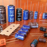
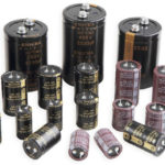
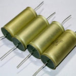
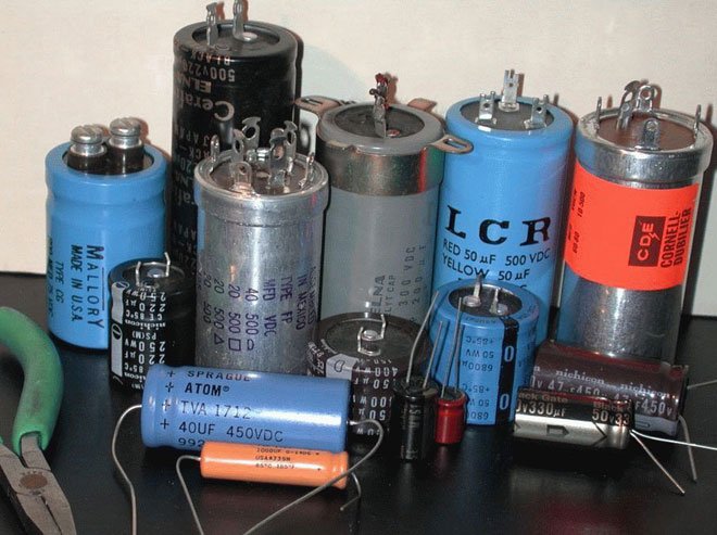
Accumulators of electric charge of constant capacity, distinguish between:
- ceramic;
- paper;
- mica;
- metal-paper;
- electrolytic capacitors.
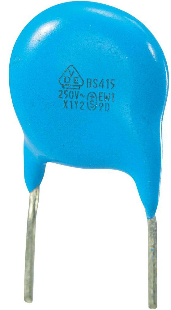
They are divided into 2 groups: low voltage and high voltage. They are used in rectifier filters, for communication between low-frequency sections of circuits, in power supplies for various devices, etc.
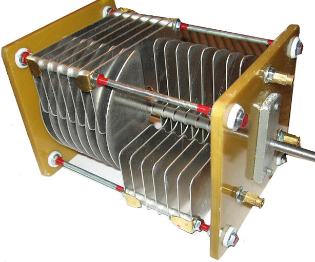
Variable capacitors also exist. They found their purpose in tuned oscillatory circuits of television and radio receivers. The capacity is adjusted by changing the position of the plates relative to each other.
Consider the connection of capacitors when their terminals are connected in pairs. Such an inclusion is suitable for 2 or more elements designed for the same voltage. The rated voltage, which is indicated on the body of the part, must not be exceeded. Otherwise, a breakdown of the dielectric will occur, and the element will fail. But in a circuit where there is a voltage less than the nominal, the capacitor can be turned on.
Parallel connection of capacitors can increase the total capacitance. In some devices, it is necessary to provide a large accumulation of electric charge. There are not enough existing denominations, you have to make parallels and use what is at hand. Determining the total value of the resulting compound is simple. To do this, you just need to add the values \u200b\u200bof all the elements used.
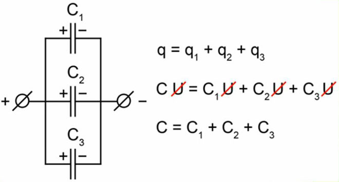
To calculate the capacitances of capacitors, the formula is:
Ctot = C1 + C2, where C1 and C2 are the capacity of the corresponding elements.
If C1=20 pF and C2=30 pF, then Ctot = 50 pF. There can be n-th number of details in a parallel.
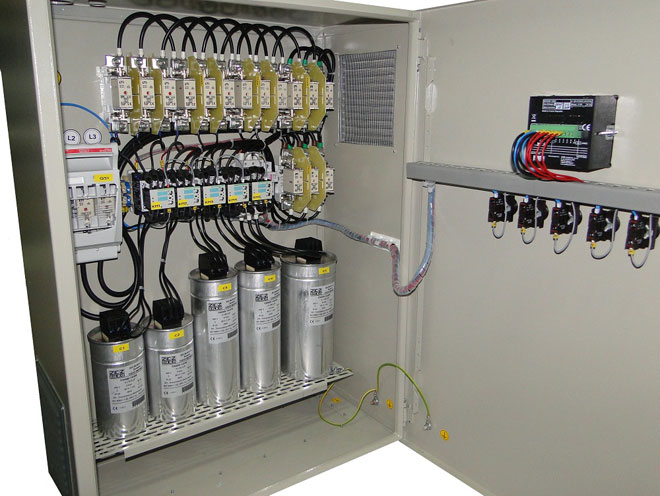
In practice, such a connection finds application in special devices used in power systems and in substations.They are mounted, knowing how to connect capacitors to increase capacity, into whole blocks of batteries.
In order to maintain the balance of reactive power both in power supply installations and in energy consumer installations, there is a need to include reactive power compensating devices (RPC). To reduce losses and adjust the voltage in the networks, when calculating the device, it is necessary to know the values of the reactances of the capacitors used in the installation.
It happens that it becomes necessary to calculate the voltage across the capacitors using the formula. In this case, we will proceed from the fact that C=q/U, i.e. charge to voltage ratio. And if the amount of charge is q, and the capacity is C, we can get the desired number by substituting the values. It looks like:
U=q/C.
mixed connection
When calculating a chain, which is a combination of the combinations discussed above, do the following. First, we look for capacitors in a complex circuit that are connected to each other either in parallel or in series. Replacing them with an equivalent element, we get a simpler circuit. Then, in the new scheme with sections of the chain, we carry out the same manipulations. We simplify until only a parallel or series connection remains. We have already learned how to calculate them in this article.
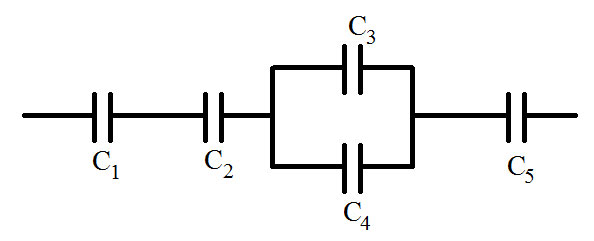
Parallel-series connection is applicable to increase the capacity, the battery, or to ensure that the applied voltage does not exceed the operating voltage of the capacitor.
Similar articles: