Projects of all electrical networks are created on the basis of special technical documentation, which displays the calculated and operating capacities, parameters and characteristics of the project of electrical networks of a room or building as a whole. All this documentation is regulated "Rules for the technical operation of consumer electrical installations". The rules are developed on the basis of the current legislative acts, state standards and other normative and technical documents. The rules of technical operation take into account the proposals of electrical repair organizations and research institutes. The fundamental document in the design documents is the power supply scheme.

Content
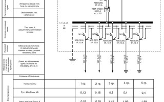
Single-line power supply diagram: what is it and why is it needed
Circuit diagram
A complete picture of how an electrical product or object functions is given by a circuit diagram. It includes the entire list of elements that make up the object. This scheme is the basis for the development of all subsequent documents and drawings necessary for the construction of an object or equipment. The circuit diagram reflects the drawings that show the complete electromagnetic and electrical connections of the elements, as well as the characteristics of all components of the object. Schematic drawing up is done in two ways: combined and separated.
With the split method use circuits that contain many contactors, relays and various contacts. To create such schemes, the elements are assigned values sequentially. But the individual circuits are placed in parallel. All parts that are part of the elements and devices or individual elements on the diagram are drawn separately from each other so that the diagram looks more visual.
With the combined method on the power supply diagram, all parts of elements or devices are displayed close to each other.
On the free fields of the schemes, which are made in a spaced way, it is permissible to place graphic symbols of devices made in a combined way.
If the object contains elements that are partially used, then these elements must be shown in full on the diagram, and it should be indicated which parts are used in their entirety and which are not. Those that are fully used should be displayed longer on the diagram, and parts of unused elements should be displayed shorter.
What is meant by a single line diagram
A single-line diagram differs from a circuit diagram in that on a single-line diagram, all electrical connections of an object are made in a simplified form and are indicated by one line, regardless of the number of phases. This simplification method is used not only to display power lines, but also to indicate a different type of cable, the number of wires in which can be more than three.
Types of single-line diagrams: calculated and executive
Design scheme used at the stage of design and selection of electrical equipment. It serves as the basis for other schemes necessary for the construction of the facility and its commissioning. When drawing up the design scheme, all the necessary parameters are taken into account that will provide the facility with complete fire safety.
On the finished object executive scheme used when electrical networks are subject to modernization. In this case, the drawing is developed on the basis of existing installations. Before drawing up a single-line power supply scheme, a comprehensive survey of the facility is mandatory. The upgraded scheme is developed taking into account the correction of all defects that were identified during the work.
Key points for designing a single-line power supply circuit
What should include a single-line power supply scheme
To put the facility into operation, the sequence of the following actions is required:
- make a request for technical specifications to the power grid organization;
- develop a one-line diagram;
- approve the finished scheme in the organization that issued the technical specifications.
Stages of approval of the executive scheme exactly the same, as well as for the calculated one.
In order to easily go through all the stages of preparing a single-line diagram, it must contain information of the following nature:
- main and backup point of connection to the power grid;
- type of input-distributing device;
- electricity meters;
- laying methods wires and cables, indicating brand and length;
- automatic shutdown devices and their technical parameters;
- load on the power grid with indication of power and current strength;
- lighting circuits.
Registration rules, GOST requirements
When designing single-line diagrams, it is imperative to comply with the requirements of GOST ESKD (Unified system of design documentation), in which the algorithm for creating electrical circuits:
- GOST 2.702-2011 - provisions for the development of electrical circuits;
- GOST 2.709-89 - wires, contact connections and sections of circuits;
- GOST 2.755-87 – switching devices and contact connections;
- GOST 2.721-74 – designations of general application;
- GOST 2.710-81 - alphanumeric characters.
The thickened line on the diagrams highlights all electrical elements and power circuits.
All electrical circuits must be marked. It is necessary to assign marking from the source to the consumer sequentially. The chains are designated with Arabic numerals and capital Latin letters. The numbers indicate the sequence of the chain, and the letters — AC phase.
Circuit sections with separated contacts (relay windings, resistors etc.), must be marked with regard to polarity. The positive polarity of the circuit sections is indicated by odd numbers, the polarity with negative values — even.
The sections of the circuit that pass through different contact connections must have the same designation. The marking on the diagram is described on the left or above the circuit image.
The diagram must indicate the full characteristics of the input and output electrical circuits. Characteristics include voltage, resistance, frequency, inductance, current, etc.
All parameters of electrical circuits, connection addresses can be written in tables to simplify reading the diagram. The tabular version replaces the schematic designations of input and output elements. When constructing a diagram, the table looks more visual, it is performed in an arbitrary form, because it is not regulated by GOST.

If a table is placed in place of the element, then the positional designation of the element is assigned to it, instead of the symbols for the drawings.
When performing a single-line diagram, it is permissible to place technical specifications in the form of text in the free field of the diagram:
- brands, sections and colors cables and wires, connecting the elements of the product;
- installation requirements;
- assignment of individual circuits.
If the diagram is made on several sheets, then certain requirements must be taken into account:
- registration of a general list of all elements;
- within the product, all positional designations of elements must have continuous numbering.
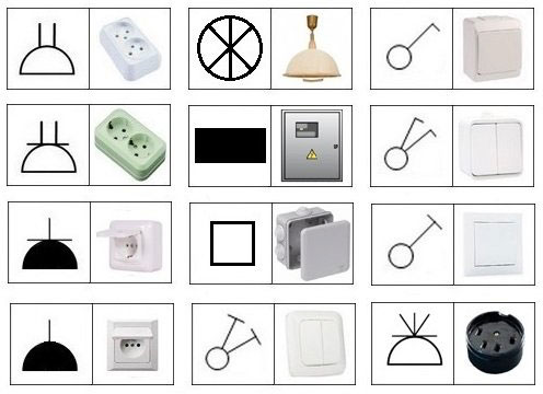
Conventions used in the preparation of single-line diagrams
All elements of energy supply are strictly determined by regulatory documents and GOSTs. Each element has its own conventionsthat are reflected in the drawings.
- rectangles designate all guards;
- rectangles with a bar at the bottom — these are panel elements of highways;
- black rectangles — these are group shields;
- rectangles with two diagonals — these are emergency connection boards;
- a square with a line at the bottom designate distribution cabinets and panels of one-way service;
- a square with a line at the bottom and at the top designate distribution cabinets and double-sided service panels;
- square with thick vertical line denotes a pull box;
- a circle with a thickened cross line and a line from the center of the circle to the bottom — this is a junction box;
- a circle from which a line extends diagonally upwards to the right — this is switch, if there are several poles, then there will be as many lines as there are poles;
- a circle from which a line extends diagonally to the right — this is an open installation, if there are several elements, then there will be as many lines as there are elements;
- a circle from which a crossed line extends diagonally to the right — this is a hidden installation, if there are several elements, then there will be as many crossed lines as there are elements;
- black circle — switch with high degree of protection;
- circle with opposite diagonals up and right and down and left — it is a switch with different directions
- a semicircle with a flat side at the bottom and a line that extends upwards from the top of the semicircle indicates a power outlet;
- semicircle with two lines up — socket outlet with two poles;
- semicircle with one or two lines up and additional horizontal — socket outlet with protective contact;
- semicircle with a line from the center to the top — socket outlet with concealed installation;
- black semicircle — power socket with strong protection.

Designations of lighting fixtures:
- circles — lamps;
- circle divided into 6 parts — chandelier;
- long rectangle — lamps with fluorescent lamps;
- a circle in the center with a transverse dotted line and a bold line — cable;
- circle, to the left of which the letter T is turned on its side — outdoor lighting devices;
- blackened triangle with a V-fork at the top — lamp wall cartridge;
- circle crossed with diagonals — outboard cartridge
- a circle crossed out by diagonals only on the outside of the circle - ceiling cartridge;
- circle with letter A — ammeter;
- circle with letter V — voltmeter;
- circle with up arrow inside circle - galvanometer;
- a square with a t inside and an arrow to the right — temperature sensor;
- square with the letter N and the image of a lightning bolt — oscilloscope;
- a tall rectangle with a separated top segment and the letters Wh — electric meter.
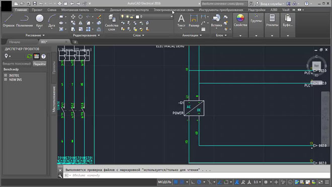
Special programs for drawing single-line power supply diagrams
For the correct execution of technical documentation, you need to study the requirements of GOSTs, but you can use specially designed computer programs. When using specialized programs, all requirements will be taken into account automatically.
- "1-2-3 scheme" — very easy to understand free program. Suitable for students and beginners;
- "AutoCAD Electrical" — a very popular program among experienced professionals, which is understandable and provides advanced opportunities for the development of electrical circuits;
- "Microsoft Vision" — a free program for ordinary people who use the program to draw up a power supply scheme during the construction of a private house;
- XL Pro² — free software for designing low-voltage complete devices (NKU);
- "Compass-Electric" — free program for engineers and specialists of energy complexes;
- Rapsodie — another program for designing low-voltage complete devices. The program allows you to easily assemble the desired switch cabinet according to the specified parameters;
- Eagle — the program is available in a free and paid version, a more advanced version in terms of technical parameters is available in a paid package;
- "DipTrace" — software for creating electrical circuits, drawings of printed circuit boards for creating electronic products.
In order to competently and clearly develop a single-line diagram, it is necessary to be strictly guided by GOSTs and standards, be able to use modern software products and have an idea about electrical installations, but it is best to use the services of a specialist.
Similar articles: