Proper connection of the electric stove, taking into account the necessary standards, is required for efficient operation and an increase in the service life. A specialist is invited to connect the power, but you can work on your own and save money. Studying the instructions attached to the unit will help to avoid errors and unpleasant consequences. When connecting an electric stove with your own hands, the regulatory characteristics of appliances, wires, sockets and plugs are taken into account.

Content
Requirements for the parameters and ratings of circuit breakers
Household electric stoves are a powerful type of equipment that uses a current of 40 to 50 A for operation. They are connected to a separate cable that is directly powered from a common house panel. Electricity is supplied through a circuit breaker and RCD. The unit itself is connected through a plug and socket, as well as a terminal box.The branch from the machine starts directly on the clamps located on the wall behind the stove.
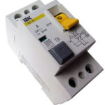
A residual current device (RCD) is a device for powering and cutting off the supply of energy under certain conditions when the differential current reaches the specified parameters. The sensor protects people and animals from electric shock in case of minor damage to the insulation and current-carrying phase conductors.
In the switchboard, a set is assembled from an RCD circuit breaker, from here the voltage goes to the outlet. Designs are sold that combine the functions of 2 devices in one device. The minus is connected to a common bus, and grounding goes to the corresponding contact.
The rating of the machine is selected according to the current consumption. The indicator is in the passport of the stove and is 40 - 50 A. To work in this range, protective devices are presented in 3 denominations:
- 63 A;
- 50 A;
- 40 A.
It is recommended to take a power device with a large indicator. This will help to avoid regular shutdowns when working at full load. If the maximum declared consumption in the passport is 42-44 amperes, then protection is taken at 50 A. The equipment may not always work at full capacity, for this all burners and the oven must function, but it is better to play it safe.
The best indicator for choosing an RCD is the current limit 1 step higher from the characteristics of the machine. If a 50 A device is installed, then a 63 A protection device is required, and the leakage current is calculated at 30 mA.
To increase reliability, the plate is connected directly to the input terminals, while using the minimum number of contact points. The termination of work is carried out only automatically, which is inconvenient. Often the oven is connected using a plug and socket, which is more familiar.For this, power pairs are used, household ones are not suitable.
Wire and its parameters
Modern hobs for installation in an apartment are sold without a cord. The complete set serves as a guarantee that the devices are joined by means of clamping blocks. In this case, the length of the supply cable increases, the machine changes to a fusible link. The section is chosen depending on the length:
- if the length of the wire does not exceed 12 m, then it is enough to take a cable with a cross section of only 4 mm²;
- when extending the supply cord, a value of 6 mm² is required.
These are generalized values, since the characteristic changes up or down when the power changes. For 7 kW ovens, a 3x4 cable is used, the line is equipped with a 25 A automatic machine. The choice of the number of cores depends on the phase connection option:
- a single-phase circuit is performed using a three-wire electrical wire;
- two-phase and three-phase connections are made using a five-core cable that has a cross section of at least 2.5 mm² and feeds equipment up to 16.4 kW.
A five-core cable with such indicators is suitable for all household electric stoves. When laying power to the outlet, a single-core wire with factory insulation is used, as it is reliable, despite its rigidity. Due to the latter characteristic, it is not used to connect to the clamps on the back wall, since this is inconvenient to do.
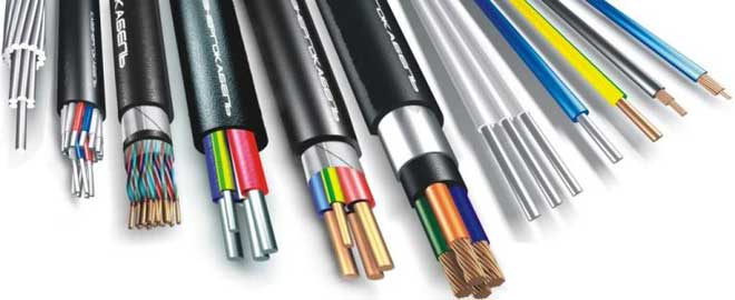
For laying from the junction box to the plate, cable brands are taken:
- VVG;
- PVA;
- VVG-ng;
- ShVp.
To connect to the outlet, a flexible KG wire is used, which is characterized by resistance to cracking when turning.
Scheme and connection methods
A single-phase connection of the stove is common.To connect the electric stove in this way, terminals 1,2,3 and then 4.5 are combined with copper jumpers with a cross section of more than 6 mm². These items are included in the sales package. The phase conductor is painted black, brown or gray and is connected to terminal 1, 2 or 3. The neutral wire of the blue color must be connected to terminal 5 or 4. The green ground braid is attached to pin 6.
The bolts are tightened with force, because poor-quality docking leads to burning of the insulation and fire. In the variant of the electric stove connection diagram, when powered from a socket, the phase wire is attached to the L terminal, the zero goes to the N terminal. The ground wire is connected to the corresponding contact, which is shown in the grounding pattern, with the letters PE.
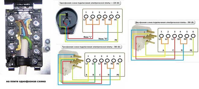
The two-phase circuit is rarely used. Before you connect the stove correctly, you need to determine that phase B is not used, there are only A and C. Clamps 1, 2 are closed with a copper jumper, work wire A is attached to them, phase C goes to terminal 3. Further connection is similar to the single-phase method. A two-phase circuit is used in private buildings, but this option is not excluded in apartments if the wiring is made with a four-wire cable. Correct wiring connection:
- the yellow wire goes to the terminals L1 and L2 connected by a jumper - phase A;
- the red wire is attached to the clamp L3 - working circuit C;
- the blue braid is joined to the zero contact - the zero circuit;
- green color - grounding.
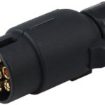
There are 4 horns on the fork in this version.
The hob and oven are connected in a three-phase circuit, the method is used as an option for connecting an electric stove in private households or old-type high-rise buildings.A 4- or 5-wire wire is taken, while between the phase and zero the voltage is 220 V, and in the middle of the working phases the indicator is 380 V. The connection takes place in the following order:
- energized conductors C, B, A are attached to the clamps with the numbers 3, 2 and 1, respectively;
- terminals 5, 4 and 6 are connected as in the single-phase version.
How to connect to a 220 V network?
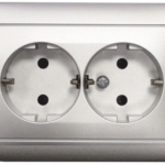
To connect the electric stove, first determine the installation location in the cart. Not far from the stove, on the nearest partition or wall, a socket is mounted, it is connected to ground. The current rating in the device is in the range from 25 to 40 A. The three-phase network socket has 5 pins. In the switchboard for the stove, an automatic machine is provided separately; a three-way switch rated for 16 A is required.
To connect, take a wire, socket and plug. Different models of household stoves are joined in the same way, only the shape of the protective covers on the back wall differs. When connecting the plates to a single-phase network, you need to run the cable to the outlet in accordance with the selected scheme and close the top cover.
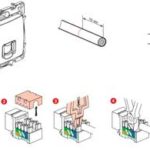
Connecting the cable to the electric stove
When using a three-wire wire, the brown braid goes to the phase connector of the socket, the blue wire is joined to the zero contact, the green-yellow wire is attached to the ground terminal. The phases of the five-core wire are white, brown and red.
The cable is connected to the tile by means of a terminal panel on the back of the equipment. Nearby are standard connection diagrams for various types of networks. For the 220 V line, the drawing on the right is used. A jumper is placed on the first 3 contacts, a phase is obtained (brown and red wires). Connectors 5 and 4 designate a neutral wire or zero (cores of blue or light blue color).The ground current flows through the green braid.
Jumpers are often installed at the factory, but when connected, the hobs are checked with a screwdriver with an indicator. The ends of the wires are tinned before joining to ensure reliable contact.
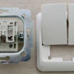
Plug installation
The plug is joined to the soft wire of the hob, taking into account the markings on it. Connecting the wires by color is done in the same way as it was done in the outlet. The power plug is always disassembled, for this, 2 screws, a cover and a fixing bar are removed. The edges of the wire cores are stripped of insulation and fastened with bolts. It is necessary to install an outlet and connect the plug so that the top green contact - ground - matches.
It is necessary to achieve the coincidence of zero and phase on the socket and plug, otherwise a short circuit will occur. Before turning on the power, once again check the correctness of the wires. If the stove is connected to a ready-made outlet, then the wire with the load, zero and ground are determined, and in the equipment the connection is made taking into account the existing manual.
The rated current of the socket is 7 kW, in some cases this is a disadvantage, because the total power when all the burners and the oven are turned on exceeds the indicator. This disables the socket-plug pair after a short period of operation. To prevent this, they take devices from Belarusian manufacturers that can withstand up to 10 kW of power at the same time.
Connection to a three-phase network 380 V
This option is beneficial, because it reduces the consumption of metal on the supply wires. Most cooking units with a large plate power are included in single-phase wiring without modifications.It is allowed to connect to 2 working wires, but it is recommended to use 3 contacts of a three-phase network 380. This reduces the load on the electrical panel devices.
Powerful stoves that require such a scheme are installed in institutions or private buildings with a 3-phase input rated for 360 V. A five-core cable with a cross section of at least 2.5 mm² is used. Before connecting the electric stove to a three-phase outlet, take a plug with 5 cores. On the terminal panel, remove the jumper from the terminals L2, L3, L1 and attach the working wires to these contacts.
In the case of connecting the oven with your own hands, the jumper between terminals 5 and 4 is left untouched, and ground is attached to terminal 6. A circuit breaker and an RCD device are purchased for a three-phase network, a five-core cable is taken. The socket and plug are bought with 5 pins.
The connection is made by a two-phase or three-phase method, the connection process differs only in the number of phase wires, which are connected differently to the output terminals on the plate block. The connecting wire is thrown only on terminals 6 and 5, the rest are connected by separate wires. Matching the colors of the phase conductors is optional, since this does not upset the functionality.
For a two-phase connection, you can take a socket with 4 pins. On foreign equipment there is a connection diagram without the use of zero. This option is provided only for America and is not used in our network, since the voltage in the line must be 110 V.
Similar articles: