Grounding issues in a private house, circuit calculations and system installation require a mandatory solution to ensure the safety of living. Grounding will perform its functions to the full only if the circuit is chosen correctly and all norms and requirements are observed. Self-assembly requires knowledge of design principles and manufacturing rules.
Content
- 1 Do I need grounding in a private house
- 2 Grounding schemes: which one is better to do
- 3 What is a ground loop: definition and device
- 4 Types of ground loops
- 5 Rules and requirements for the ground loop
- 6 Calculation of grounding for a private house: formulas and examples
- 7 We develop a scheme
- 8 Materials for the ground loop
- 9 How to do the installation of the ground loop yourself
- 10 Ready-made grounding kits for a private house
- 11 Features of grounding schemes 220 V and 380 V
- 12 Common mistakes when performing installation work
Do I need grounding in a private house
When using any electrical appliances in the house, there is always a risk of damage to the insulation of the wires or shorting them to the case. In this case, any person touching the danger zone leads to electric shock, which can end tragically. The current always tends to the ground, and the human body becomes a conductor connecting the damaged device to the ground.
What does grounding provide? In fact, this is a system that provides the shortest path for electric current. According to the law of physics, he chooses the conductor with the least electrical resistance, and the circuit has this property. Almost all of the current is directed to the ground electrode, and therefore only a small part of it will pass through the human body, which cannot cause harm. Thus, the ground loop provides electrical safety. Regulatory documents (GOSTs, SNiP, PUE) indicate that any private, residential building must be equipped with them with AC networks at a voltage above 40 V and AC networks above 100 V.
In addition to ensuring safety, the grounding system increases the reliability and durability of household appliances. It ensures stable operation of installations, protection against overvoltages and various interferences in the network, reduces the impact of external sources of electromagnetic radiation.
Grounding should not be confused with lightning rods (lightning rods). Although the principle of their operation is similar, they perform a different task. The work of a lightning rod is to divert a lightning discharge to the ground when it hits a house. In this case, a powerful electric charge arises, which should not fall into the internal network, because.can simply melt the wire or cable. That is why the lightning rod line runs from the receivers on the roof along the outer contour and should not be combined with the grounding, inner line. The lightning rod and grounding may have a common underground circuit (if it has a margin), but the wiring must be separated.
Grounding schemes: which one is better to do
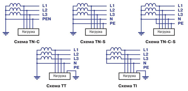
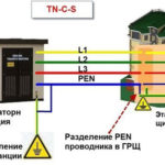
The grounding system of a private house depends on the type of network connection to it. Most often, it is performed according to the TN-C principle. Such a network is provided with a two-wire cable or a two-wire overhead line at a voltage of 220 V and a four-wire cable or a four-wire line at 380 V. In other words, the phase (L) and the combined protective-neutral wire (PEN) are suitable for the house. In full-fledged, modern networks, the PEN conductor is divided into separate wires - working or zero (N) and protective (PE), and the supply is carried out by a three-wire or five-wire line, respectively. Given these options, the grounding scheme can be of 2 varieties.
TN-C-S system
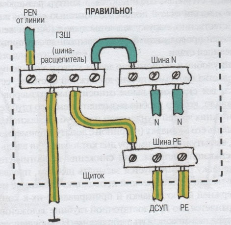
Provides for the division of the PEN-input into parallel conductors. To do this, in the input cabinet, the PEN conductor is divided into 3 buses: N (“neutral”), PE (“ground”) and a splitter bus into 4 connections. Further, the conductors N and PE cannot contact each other. The PE busbar is connected to the cabinet body, and the N-conductor is installed on the insulators. The ground loop is connected to the splitter bus. A jumper with a cross section of at least 10 sq. mm (for copper) is installed between the N-conductor and the ground electrode. In further wiring, "neutral" and "ground" do not intersect.
Reference! It is important to consider that this system is only effective when installing an RCD and a differential type circuit breaker.
TT system
In such a circuit, it is not required to split the conductors, because. the neutral and earth conductor are already separated in a suitable network. In the cabinet, the correct connection is simply made. The ground loop is connected to the (core) PE wire.
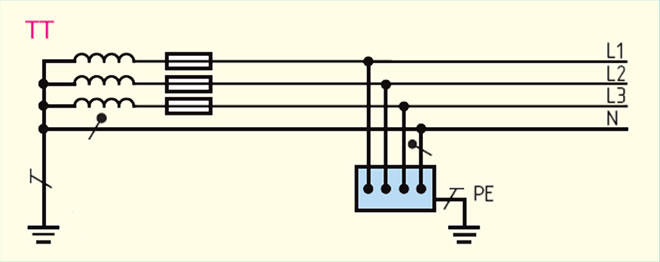
The question of which grounding system is better does not have a clear answer. The CT circuit is easier to install and does not require additional protective devices. However, the vast majority of networks operate on the TN-C principle, which forces the use of the TN-C-S scheme. In addition, electrical installations with two-wire power are often used in everyday life. When grounding the CT, the case of such devices is energized if the insulation is damaged. In this case, the TN-C-S grounding is much more reliable.
What is a ground loop: definition and device
The ground loop is a special design of electrically conductive materials with low electrical resistance, providing an instantaneous discharge of electrical current to the ground. It consists of 2 interconnected parts - internal and external system. Their reliable connection is carried out in the input electrical panel.
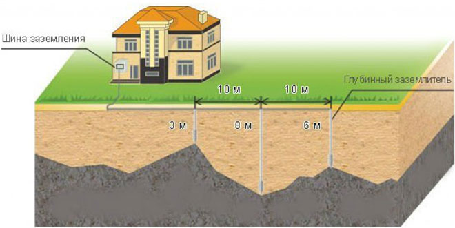
The device of the external subsystem must ensure the transition of the electrical signal to the ground with its distribution over the area. It is based on several electrodes buried in the ground and connected to each other in a circuit using plates. A bus of sufficient cross section departs from the plates, which is introduced into the electrical panel, where it is connected to the internal subsystem. Each electrode is a metal pin buried (driven in) to a certain depth.
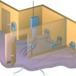
The internal subsystem is the wiring of the ground circuit throughout the house. The conductors from the shield are diverted to sockets, to the cases of powerful electrical devices, to metal lines (pipes). Separate conductors are combined into a common bus, which is connected to the bus of the external circuit.
The principle of operation of the ground loop is quite simple. The electric charge accumulated in metal elements (plant housings, pipelines, fittings, etc.) in case of damage to the insulation of the electrical network conductors or induced from external sources, rushes along the wires of the internal subsystem, which have low electrical resistance, to the external subsystem circuit. On the electrodes buried in the ground, it "flows" into the ground. In turn, the earth has a huge capacity, which allows you to freely "absorb" such electricity leaks.
Types of ground loops
To quickly "drain" the current into the ground, the external subsystem redistributes it to several electrodes arranged in a certain order to increase the dissipation area. There are 2 main types of connection in the circuit.
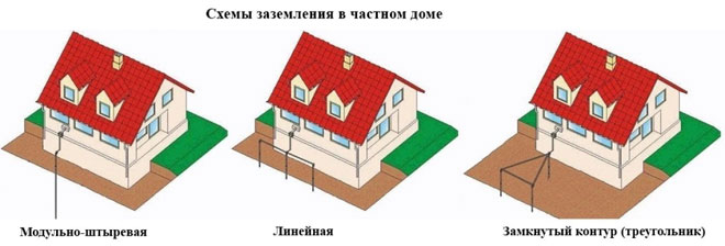
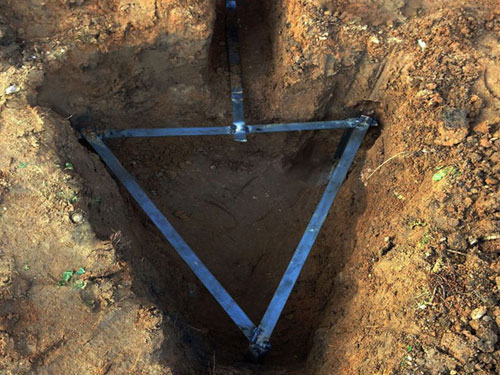
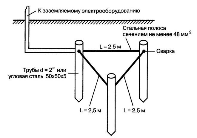
Triangle - closed loop
This case involves the use of 3 pins connected by stripes in an isosceles triangle. The distance between the electrodes is selected according to the following principle: the minimum distance is the length of the underground part of the electrode (depth), the maximum is 2 depths. For example, for a standard depth of 2.5 m, the side of the triangle is selected within 2.5-5 m.
Linear
This option is made up of several electrodes arranged in a line or in a semicircle. An open contour is used in cases where the area of \u200b\u200bthe site does not allow the formation of a closed geometric figure.The distance between the pins is selected within 1-1.5 depth. The disadvantage of this method is an increase in the number of electrodes.
These types are most often used in arranging the grounding of a private house. In principle, a closed loop can be formed in the form of a rectangle, polygon or circle, but more pins will be required. The main advantage of closed systems is the continuation of full operation when the bond between the electrodes is broken.
Important! The linear circuit works on the principle of a garland and damage to the jumper decommissions a certain section of it.
Rules and requirements for the ground loop
In order for the ground loop to work effectively, it must comply with certain rules:
- The external contour should be located at a distance of at least 1 m and not more than 10 m from the house. The optimal distance is 2-4 m from the foundation.
- The depth of the electrodes is selected within 2-3 m. A part of the pin 20-25 cm long is left on the surface for connection with a strip.
- From the inlet shield to the circuit, a bus with a cross section of at least 16 square meters is laid. mm.
- Linking the electrodes to each other is provided only by welding. In the shield, the connection can be made with bolts.
- The total system resistance must not exceed 4 ohms for 380V and 8 ohms for 220V.
The external ground loop is located in the ground, which implies increased requirements for its design. It should be located below the freezing level of the soil, because. swelling of the soil will push the electrodes out. During operation, corrosion should not destroy the metal and excessively increase its electrical resistance. The strength of the rods should allow them to be driven into solid ground.
Calculation of grounding for a private house: formulas and examples
Grounding calculations for a private house are based on the formulas for calculating the resistance to current spreading for electrodes. Examples will be shown below.
Ground resistance
With a single rod, the formula is applied:
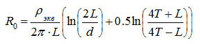
where ρ equiv is the equivalent resistivity of a single-layer soil (selected according to Table 1 for a specific soil);
- L is the length of the electrode (m);
- d is the electrode diameter (m);
- T is the distance from the middle of the electrode to the ground surface (m).
Table 1
| Priming | ρ equiv, Ohm m |
|---|---|
| Peat | 20 |
| Soil (chernozem, etc.) | 50 |
| Clay | 60 |
| sandy loam | 150 |
| Sand with groundwater up to 5 m | 500 |
| Sand with groundwater deeper than 5 m | 1000 |
Dimensions and distances for earth electrodes
The number of electrodes in the circuit can be calculated by the formula, where:

Rн - the maximum allowable total resistance of the circuit (for a network of 127-220 V - 60 Ohm, for 380 V - 15 Ohm), Ψ - climatic coefficient (determined according to table 2).
table 2
| Electrode type | Climate zone | |||
|---|---|---|---|---|
| I | II | III | IV | |
| vertical rod | 1.8 ÷ 2 | 1.5 ÷ 1.8 | 1.4 ÷ 1.6 | 1.2 ÷ 1.4 |
| horizontal bar | 4.5 ÷ 7 | 3.5 ÷ 4.5 | 2 ÷ 2.5 | 1.5 |
The dimensions of the electrodes are selected taking into account real conditions and recommendations:
- pipe - minimum wall thickness 3 mm, diameter - according to the presence of material;
- steel bar - diameter not less than 14 mm;
- corner - wall thickness 4 mm, size - according to the presence of material;
- strip for linking electrodes - width - not less than 10 mm, thickness - more than 3 mm.
The depth of penetration (the length of the electrodes) is selected from the condition - at least 15-20 cm below the freezing level. The minimum length is 1.5 m. The spacing of the pins is 1-2 electrode lengths, and the minimum distance is 2 m.
We develop a scheme
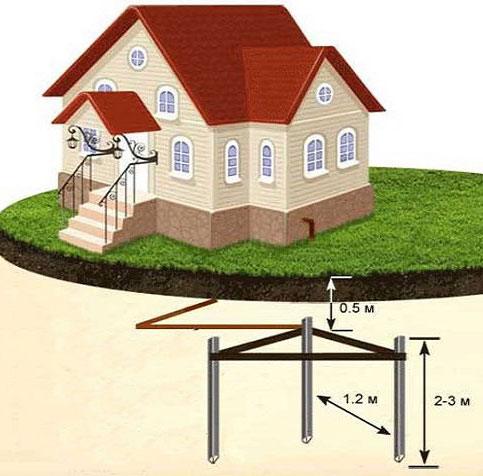
Work on arranging the grounding of a private house begins with the development of a ground loop circuit. The most popular is a closed system in the form of a triangle. Three electrodes make up its vertices, and the remaining rods are dug into its sides between the vertices. If the area near the house does not allow the construction of such a circuit, then the electrodes are installed in a line, in a semicircle or in a “wave”. It should be noted that the efficiency of the triangular arrangement is much higher.
Materials for the ground loop
The ground loop must have high mechanical strength, low electrical resistance and the possibility of a reliable connection. In addition, an important role in the choice of material is played by its cost.
Parameters and materials of pins
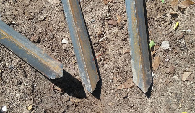
Electrodes or pins are usually made from a steel profile. This material attracts with the possibility of deepening the rods by simply driving them in. At the same time, its electrical resistance fully satisfies the requirements with a sufficient cross section. Pins can be made from the following materials:
- Bar. The most common option is a rod with a diameter of 16-18 mm. It is not recommended to use fittings, because. it is heated, which leads to an increase in resistivity. In addition, the corrugated surface leads to irrational use of the rod section.
- Corner. The most commonly used corner is 50x50 mm in size with a wall thickness of 4-5 mm. The lower part is pointed for easier clogging.
- Pipe with a diameter of more than 50 mm with a wall thickness of 4-5 mm. Thick-walled pipes are recommended for hard ground and regions with frequent droughts. Holes are drilled in the lower part of such a pin.When the soil dries out, salt water is poured into the pipe, which increases the scattering ability of the soil.
What to make a metal bond
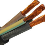
Electrodes hammered into the ground are interconnected by a metal bond. It can be made from the following materials:
- Copper bus or wire with a cross section of at least 10 mm2.
- Aluminum strip or wire with a cross section of at least 16 mm2.
- Steel strip with a cross section of at least 48 sq. mm.
The most commonly used steel strip is (25-30)x5 mm in size. Its main advantage is the possibility of reliable welding with electrodes. When a non-ferrous conductor is used as a connection, bolts are welded to the pins, on which the tires are fixed.
How to do the installation of the ground loop yourself
Installation of grounding can be done by hand. All steps will be described below.
Choose a place
It should be located in that part of the site near the house where a person does not go without urgent need and pets. The contour is located no closer than 1 m from the foundation of the building. It is better if this site is fenced with a low fence. All points of location of electrodes are marked on the ground. Usually a regular, isosceles triangle is built.
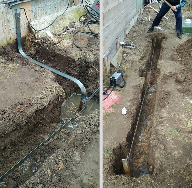
Excavation
A trench 0.5-0.6 m deep is dug along the entire marking.
Assembling the structure
First, according to the scheme, the pins are driven in to a given depth (usually 2-2.5 m). A metal bond is welded to the tops of the rods. One strip is welded to the extreme electrode (the top of the triangle) and placed in a trench leading to the house.
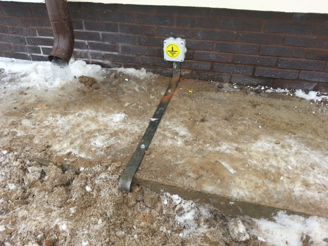
Entering the house
The bus from the circuit is introduced into the input electrical panel. A hole is drilled at the end for a bolted connection. The corresponding cable core is connected here. With a TN-C-S system, the bus is connected to a splitter bus.
Check and control
Control is carried out by measuring the electrical resistance of the entire circuit. It should not exceed the standard values
A simple verification method is often used. An incandescent lamp with a power of 100-150 W is connected - one end per phase, the other - to ground. Its clear radiance indicates a quality installation. With dim burning, it is necessary to check the quality of the joints. If the lamp does not light up, then the assembly was not carried out correctly.
Ready-made grounding kits for a private house
Self-assembly can significantly reduce the cost of the grounding system. However, ready-made kits allow you to speed up work and increase the reliability of the circuit. The following models can be distinguished:
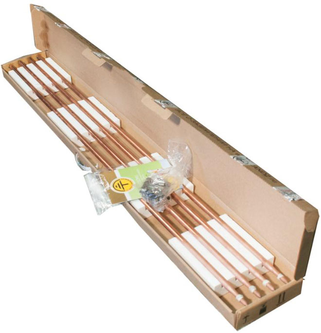
- ZandZ – circuit with one or more stainless steel electrodes. Permissible penetration - up to 10 m. The price depends on the length of the pins. The average price of a set with five-meter electrodes is 23,500 rubles.
- Galmar - has electrodes up to 30 m long. The average price is 41,000 rubles.
- Elmast. This system is manufactured in Russia and adapted to Russian operating conditions. Price - from 8000 rubles.
Important! There are many models on the Russian market, which allows you to make the best choice. The depth of clogging of their electrodes ranges from 5 to 40 m. The price range is 6000-28000 rubles.
Features of grounding schemes 220 V and 380 V
Grounding schemes when entering 220 and 380 V networks have certain differences. The external contour of such systems is absolutely the same. The difference lies in the cabling and entry into the house.In the case of a 220 V network, a two-wire line is introduced. One core is split into "neutral" and "ground", and the other is installed on insulators.
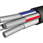
In the case of a 380 V network, a four-wire line is most often suitable. One wire is split similarly to the previous case, and 3 other conductors are installed on insulators and isolated from each other. Phase conductors and "neutral" are passed through the RCD and difavtomat.
Common mistakes when performing installation work
Experts note that during self-assembly, the following mistakes are most often made:
- An attempt to protect the electrodes from corrosion by painting. This method is unacceptable, because. prevents flow to the ground.
- Connection of a steel metal connection with pins with bolts. Corrosion quickly breaks the contact between the elements.
- Excessive removal of the circuit from the house, which significantly increases the resistance of the system.
- Application of too thin profile for electrodes. After a short period of time, corrosion causes a sharp increase in the resistance of the metal.
- Contact of copper and aluminum conductors. In this case, the connection deteriorates due to contact corrosion.
If deficiencies are found in the design, they should be eliminated immediately. An excessive increase in electrical resistance or a violation of the continuity of the circuit disrupts the operation of the ground. The circuit will not be able to guarantee safety.
A ground loop is required for a private house. This design will ensure the electrical safety of residents and eliminate tragic accidents. However, it should be remembered that the effectiveness of grounding depends on the correct calculations, the choice of circuit and the installation.If there is doubt in one's own abilities, then it is better to use a ready-made kit.
Similar articles: