Protection of electric motors, magnetic starters and other equipment from loads that cause overheating is carried out using special thermal protection devices. In order to make the right choice of a thermal protection model, you need to know its principle of operation, device, as well as the main selection criteria.
Content
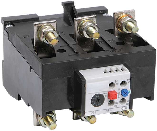
Device and principle of operation
Thermal relay (TR) is designed to protect electric motors from overheating and premature failure. During a long-term start, the electric motor is subject to current overloads, because. during start-up, seven times the current is consumed, leading to heating of the windings. Rated current (In) - the current consumed by the motor during operation. In addition, TR increases the life of electrical equipment.
Thermal relay, the device of which consists of the simplest elements:
- thermosensitive element.
- Contact with self-return.
- Contacts.
- Spring.
- Bimetallic conductor in the form of a plate.
- Button.
- Setpoint current regulator.
The temperature sensitive element is a temperature sensor used to transfer heat to a bimetallic plate or other thermal protection element. Contact with self-return allows, when heated, to instantly open the power supply circuit of an electrical consumer to avoid overheating.
The plate consists of two types of metal (bimetal), one of which has a high thermal expansion coefficient (Kp). They are fastened together by welding or rolling at high temperatures. When heated, the thermal protection plate bends towards the material with a lower Kp, and after cooling, the plate takes its original position. Basically, the plates are made of Invar (lower Kp) and non-magnetic or chromium-nickel steel (higher Kp).
The button turns on the TR, the setting current regulator is necessary to set the optimal value of I for the consumer, and its excess will lead to the operation of the TR.
The operating principle of TR is based on the Joule-Lenz law. The current is the directed movement of charged particles that collide with the atoms of the crystal lattice of the conductor (this value is the resistance and is denoted by R). This interaction causes the appearance of thermal energy obtained from electrical energy. The dependence of the duration of the flow on the temperature of the conductor is determined by the Joule-Lenz law.
The formulation of this law is as follows: when I passes through the conductor, the amount of heat Q generated by the current, when interacting with the atoms of the crystal lattice of the conductor, is directly proportional to the square of I, the value of R of the conductor and the time the current acts on the conductor.Mathematically, it can be written as follows: Q = a * I * I * R * t, where a is the conversion factor, I is the current flowing through the desired conductor, R is the resistance value and t is the flow time of I.
When the coefficient a = 1, the calculation result is measured in joules, and provided that a = 0.24, the result is measured in calories.
Bimetallic material is heated in two ways. In the first case, I passes through the bimetal, and in the second, through the winding. Winding insulation slows down the flow of thermal energy. The thermal switch heats up more at high values of I than when it comes into contact with the temperature sensing element. The contact actuation signal is delayed. Both principles are used in modern TR models.
The heating of the bimetal plate of the thermal protection device is carried out when the load is connected. Combined heating allows you to get a device with optimal characteristics. The plate is heated by the heat generated by I when passing through it, and by a special heater when I is loaded. During heating, the bimetallic strip deforms and acts on the contact with self-return.
Main characteristics
Each TR has individual technical characteristics (TX). The relay must be selected according to the characteristics of the load and the conditions of use when operating an electric motor or other consumer of electricity:
- The value of In.
- Adjustment range of I actuation.
- Voltage.
- Additional management of TR operation.
- Power.
- Operation limit.
- Sensitivity to phase imbalance.
- Trip class.
The rated current value is the value of I for which the TR is designed.It is selected according to the value of In of the consumer to which it is directly connected. In addition, you need to choose with a margin of In and be guided by the following formula: Inr \u003d 1.5 * Ind, where Inr - In TR, which should be 1.5 times more than the rated motor current (Ind).
The I operation adjustment limit is one of the important parameters of the thermal protection device. The designation of this parameter is the adjustment range of the In value. Voltage - the value of the power voltage for which the relay contacts are designed; if the permissible value is exceeded, the device will fail.
Some types of relays are equipped with separate contacts for controlling the operation of the device and the consumer. Power is one of the main parameters of the TR, which determines the output power of the connected consumer or consumer group.
The trip limit or trip threshold is a factor that depends on the rated current. Basically, its value is in the range from 1.1 to 1.5.
Sensitivity to phase imbalance (phase asymmetry) shows the percentage ratio of the phase with imbalance to the phase through which the rated current of the required magnitude flows.
Trip class is a parameter that represents the average tripping time of the TR depending on the multiple of the setting current.
The main characteristic by which you need to choose TR is the dependence of the operation time on the load current.
Wiring diagram
Diagrams for connecting a thermal relay to a circuit can vary significantly depending on the device.However, TRs are connected in series with the motor winding or the magnetic starter coil to a normally open contact, as this kind of connection allows you to protect the device from overloads. If the current consumption indicators are exceeded, the TR disconnects the device from the power supply.
In most circuits, a permanently open contact is used when connecting, which works when connected in series with a stop button on the control panel. Basically, this contact is marked with the letters NC or H3.
A normally closed contact can be used when connecting a protection alarm. In addition, in more complex circuits, this contact is used to implement software control of the emergency stop of the device using microprocessors and microcontrollers.
The thermostat is easy to connect. To do this, you need to be guided by the following principle: TR is placed after the contactors of the starter, but before the electric motor, and the permanently closed contact is switched on by serial connection with the stop button.
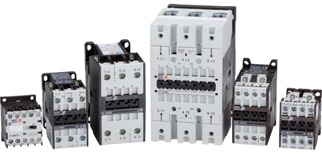
Types of thermal relays
There are many types into which thermal relays are divided:
- Bimetallic - RTL (ksd, lrf, lrd, lr, iek and ptlr).
- Solid state.
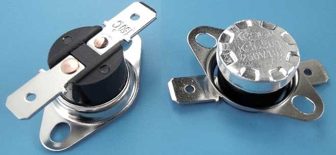
- Relay for monitoring the temperature regime of the device. The main designations are as follows: RTK, NR, TF, ERB and DU.
- Alloy melting relay.
Bimetallic TRs have a primitive design and are simple devices.
The principle of operation of a solid-state type thermal relay differs significantly from the bimetallic type. A solid-state relay is an electronic device, which is also called a Schneider and is made on radio elements without mechanical contacts.
These include RTR and RTI IEK, which calculate the average temperatures of the electric motor by monitoring its starting and In. The main feature of these relays is the ability to resist sparks, i.e. they can be used in explosive environments. This type of relay is faster in operating time and easier to adjust.
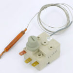
RTCs are designed to control the temperature regime of an electric motor or other device using a thermistor or thermal resistance (probe). When the temperature rises to the critical mode, its resistance increases sharply. According to Ohm's law, as R increases, the current decreases and the consumer turns off, because. its value is not enough for the normal operation of the consumer. This type of relay is used in refrigerators and freezers.
The design of the thermal melting relay of the alloy differs significantly from other models and consists of the following elements:
- Heater winding.
- An alloy with a low melting point (eutectic).
- chain breaking mechanism.
The eutectic alloy melts at a low temperature and protects the consumer's power circuit by breaking contact. This relay is built into the device and is used in washing machines and automotive technology.
The selection of a thermal relay is made by analyzing the technical characteristics and operating conditions of the device, which must be protected from overheating.
How to choose a thermal relay
Without complex calculations, you can choose the appropriate rating of the electrothermal relay for the motor in terms of power (table of technical characteristics of thermal protection devices).
The basic formula for calculating the rated current of a TR is:
Intr = 1.5 * Ind.
For example, you need to calculate In TP for an asynchronous electric motor with a power of 1.5 kW, powered by a three-phase AC network with a value of 380 V.
This is easy enough to do. To calculate the value of the rated current of the motor, you must use the power formula:
P = I * U.
Hence, Ind \u003d P / U \u003d 1500 / 380 ≈ 3.95 A. The value of the rated current of the TR is calculated as follows: Intr \u003d 1.5 * 3.95 ≈ 6 A.
Based on the calculations, a TR of the RTL-1014-2 type is selected with an adjustable setting current range from 7 to 10 A.
If the ambient temperature is too high, set the setpoint to the minimum value. At a low ambient temperature, one should take into account the increase in the load on the motor stator windings and, if possible, do not turn it on. If circumstances require the motor to be used under unfavorable conditions, then it is necessary to start tuning with a low setting current, and then increase it to the required value.
Similar articles: