Transformer - an electronic device capable of changing operating values, measured by the transformation ratio, k. This number indicates a change, scaling of any parameter, such as voltage, current, resistance or power.
Content
What is the transformation ratio
The transformer does not change one parameter to another, but works with their values. However, it is called a transducer. Depending on the connection of the primary winding to the power source, the purpose of the device changes.
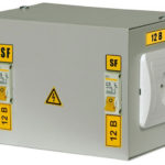
These devices are widely used in everyday life. Their goal is to supply a home device with such power that would correspond to the nominal value indicated in the passport of this device. For example, the mains voltage is 220 volts, the phone battery is charged from a 6 volt power source.Therefore, it is necessary to reduce the mains voltage by 220: 6 = 36.7 times, this indicator is called the transformation ratio.
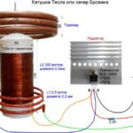
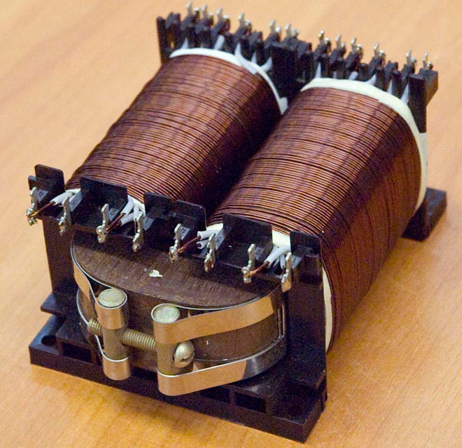
To accurately calculate this indicator, you need to remember the structure of the transformer itself. Any such device has a core made of a special alloy and at least 2 coils:
- primary;
- secondary.
The primary coil is connected to the power source, the secondary coil is connected to the load, there can be 1 or more of them. A winding is a coil consisting of an insulating wire wound on a frame, or without it. A complete turn of the wire is called a turn. The first and second coils are mounted on a core, with its help energy is transferred between the windings.
Transformer ratio
According to a special formula, the number of wires in the winding is determined, all the features of the core used are taken into account. Therefore, in different devices in the primary coils, the number of turns will be different, despite the fact that they are connected to the same power source. The turns are calculated relative to the voltage, if several loads with different supply voltages need to be connected to the transformer, then the number of secondary windings will correspond to the number of connected loads.
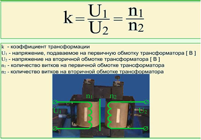
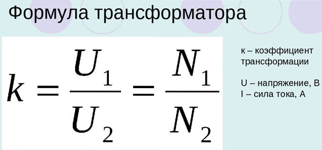
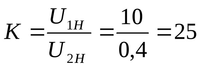
Knowing the number of turns of wire in the primary and secondary windings, k of the device can be calculated. According to the definition from GOST 17596-72 "Transformation ratio - the ratio of the number of turns of the secondary winding to the number of turns of the primary or the ratio of the voltage on the secondary winding to the voltage on the primary winding in idle mode without taking into account the voltage drop across the transformer. If this coefficient k is greater than 1, then the device is lowering; if it is less, it is increasing. There is no such difference in GOST, so a larger number is divided by a smaller one and k is always greater than 1.
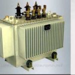
In power supply, converters help to reduce power transmission losses. To do this, the voltage generated by the power plant is increased to several hundred thousand volts. Then the voltage is reduced to the required value by the same devices.
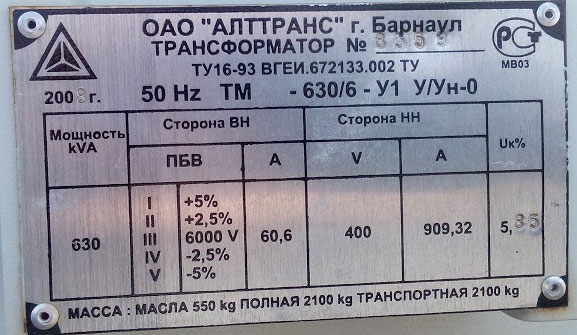
At the traction substations that provide the industrial and residential complex with electricity, transformers with a voltage regulator are installed. Additional conclusions are removed from the secondary coil, the connection to which allows you to change the voltage in a small interval. This is done by bolting or a handle. In this case, the transformation ratio of the power transformer is indicated in its passport.
Definition and formula of the transformation ratio of a transformer
It turns out that the coefficient is a constant value showing the scaling of electrical parameters, it completely depends on the design features of the device. For different parameters, k is calculated differently. There are the following categories of transformers:
- by voltage;
- by current;
- by resistance.
Before determining the coefficient, it is necessary to measure the voltage on the coils. GOST indicates that such a measurement is necessary at idle. This is when no load is connected to the converter, readings can be displayed on the nameplate of this device.
Then the readings of the primary winding are divided by the readings of the secondary, this will be the coefficient. If there is information about the number of turns in each coil, the number of turns of the primary winding is divided by the number of turns of the secondary. In this calculation, the active resistance of the coils is neglected. If there are several secondary windings, each finds its own k.
Current transformers have their own peculiarity, their primary winding is connected in series with the load. Before calculating the indicator k, the current of the primary and secondary circuits is measured. The value of the primary current is decomposed into the current of the secondary circuit. If there are passport data on the number of turns, it is allowed to calculate k by dividing the number of turns of the secondary winding wire by the number of turns of the primary wire.
When calculating the coefficient for a resistance transformer, it is also called a matching transformer, first the input and output resistances are found. To do this, calculate the power, which is equal to the product of voltage and current. The power is then divided by the square of the voltage to get the resistance. Splitting the input resistance of the transformer and the load with respect to its primary circuit and the input resistance of the load in the secondary circuit will give k of the device.
There is another way to calculate. It is necessary to find the voltage coefficient k and square it, the result will be similar.
Different types of transformers and their coefficients
Although structurally the converters are not much different from each other, their purpose is quite extensive. There are the following types of transformers, in addition to those considered:
- power;
- autotransformer;
- impulse;
- welding;
- separating;
- matching;
- peak transformer;
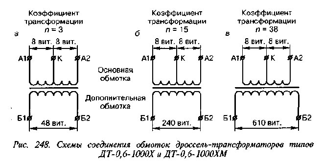
- dual throttle;
- transfluxor;
- rotating;
- air and oil;
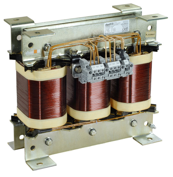
- three-phase.
A feature of the autotransformer is the absence of galvanic isolation, the primary and secondary windings are made with one wire, and the secondary is part of the primary. Pulse scales short pulsed square wave signals. Welder works in short circuit mode. Separators are used where special electrical safety is needed: wet rooms, rooms with a large number of metal products, and the like. Their k is basically 1.
A peak transformer converts a sinusoidal voltage into a pulsed voltage. A dual choke is two dual coils, but in terms of its design features it belongs to transformers. The transfluxor contains a core made of a magnetic circuit with a large amount of residual magnetization, which makes it possible to use it as a memory. Rotary transmits signals to rotating objects.
Air and oil transformers differ in the way they are cooled. Oil is used for scaling high power. Three-phase are used in a three-phase circuit.
More detailed information can be found on the transformer ratio of the current transformer in the table.
| Rated secondary load, V | 3 | 5 | 10 | 15 | 20 | 30 | 40 | 50 | 60 | 75 | 100 |
|---|---|---|---|---|---|---|---|---|---|---|---|
| Coefficient, n | Rated limit multiplicity | ||||||||||
| 3000/5 | 37 | 31 | 25 | 20 | 17 | 13 | 11 | 9 | 8 | 6 | 5 |
| 4000/5 | 38 | 32 | 26 | 22 | 20 | 15 | 13 | 11 | 10 | 8 | 6 |
| 5000/5 | 38 | 29 | 25 | 22 | 20 | 16 | 14 | 12 | 11 | 10 | 8 |
| 6000/5 | 39 | 28 | 25 | 22 | 20 | 16 | 15 | 13 | 12 | 10 | 8 |
| 8000/5 | 38 | 21 | 20 | 19 | 18 | 14 | 14 | 13 | 12 | 11 | 9 |
| 10000/5 | 37 | 16 | 15 | 15 | 14 | 12 | 12 | 12 | 11 | 10 | 9 |
| 12000/5 | 39 | 20 | 19 | 18 | 18 | 12 | 15 | 14 | 13 | 12 | 11 |
| 14000/5 | 38 | 15 | 15 | 14 | 14 | 12 | 13 | 12 | 12 | 11 | 10 |
| 16000/5 | 36 | 15 | 14 | 13 | 13 | 12 | 10 | 10 | 10 | 9 | 9 |
| 18000/5 | 41 | 16 | 16 | 15 | 15 | 12 | 14 | 14 | 13 | 12 | 12 |
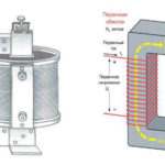
Almost all of these devices have a core for transmitting magnetic flux. The flow appears due to the movement of electrons in each of the turns of the winding, and the strength of the currents should not be equal to zero.The current transformation ratio also depends on the type of core:
- rod;
- armored.
In an armor core, magnetic fields have a greater effect on scaling.
Similar articles: