The Internet has become a part of people's lives. Thanks to new technologies, connecting to it has become easy and inexpensive. It is enough to have a desktop computer, laptop or smartphone.
Local distribution of Internet resources is carried out via a wired or wireless network. Despite the mobility of wireless connections, the prevalence of wired networks is still high. They are chosen because of their high reliability, price and safety.
It is advisable to distribute Internet cables even at the repair stage, while it is possible to hide the wires in the wall without a trace. At the same time, sockets with a special RJ-45 connector are installed at the wire exit points. Their connection to the wires is carried out by crimping the socket contacts with a special tool.
Content
Options for using RJ-45 Internet sockets
In terms of the number of wired networks, private households are leading.However, sockets for Internet cables find their application in other areas.
The performance requirements for these devices vary depending on the type of room in which they will be installed. You can conditionally divide them as follows:
- office rooms;
- Internet clubs;
- server rooms;
- places of trade;
- buildings and premises with increased protection against burglary.
No modern office building is complete without access to the Internet or a local network. So, an Internet outlet is an integral attribute of such premises. In this case, it can not only be mounted on the wall, but also attached to the workplace. The second method is preferable, since openly laid wires fail much faster and violate the aesthetic appearance of the room.
The existence of modern educational institutions is unthinkable without the presence of computer classes, Internet libraries and various multimedia devices. For this reason, an RJ45 socket in such places is no less common than an electric one.
As for bank vaults, buildings of state and corporate security services, in such places it is necessary to create wired networks, since wireless networks cannot provide adequate security.
Types and types of Internet sockets
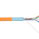
To implement a wired connection to the Internet, an RJ45 connector is used. This is a standardized physical network interface containing a description of the design of the plug, connector and a diagram of their connection to computing devices via an eight-core wire.
Such a wire is called a twisted pair.This is due to the fact that it consists of four pairs of wires intertwined, and is designed to organize network connections. Twisted pair insulation, depending on the application, is selected in different thicknesses and with different properties.
RJ-45 Internet sockets are classified as follows:
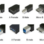
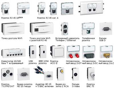
- By the number of slots. There are single, double and terminal. The latter can contain from 4 to 8 outputs. There are also combined products, or keystones. Their layout also includes other connectors: USB, HDMI and power outlets. That is, the design provides for the division into 2 outputs, one of which provides access to the network, the other provides power to the device.
- Depending on the speed of data exchange. The division is by category. The main categories are as follows: 3 - data exchange rate up to 100 Mbps; 5 - provides data transfer at speeds up to 1 Gb / s, 6 - up to 10 Gb / s.
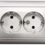
- By type of installation. As in the case of electrical outlets, fixtures are internal and overhead. For mounting an internal socket, a technological recess and a protective plastic socket in the wall under the contact group are required. The invoice has a different method of fastening. It is mounted to a pre-fixed mounting plate.
It is preferable to hide the cable for the surface socket under the plinth or in a separate cable channel. This will protect it from negative environmental influences and extend its service life.
RJ 45 cable pinout features
Connecting an RJ-45 socket should not cause any inconvenience. To make things easier, each outlet is color-coded according to the T568A or T568B standards. This information may be marked with letters corresponding to standard A or B.
It does not matter which standard is used in this case, as long as all LAN connections are made in accordance with one standard. The T568B standard has become more widespread, but this is not always the case.
In order to determine which standard the provider uses, you need to find out what the pinout is on the cable entering the room.
Another feature is the use of direct and cross pinouts, depending on the type of connected devices.
The direct line is used to establish communication between consumer devices and the router. Cross connects devices with similar functionality (PC-PC, router-router).
RJ-45 connection
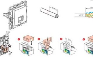
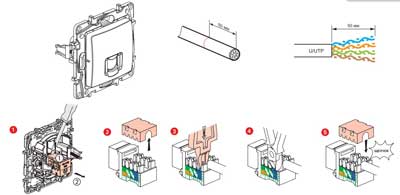
The twisted pair is hidden in the cable channel or under the plinth. The end of the wire (in the case of flush mounting) is led out through the socket or simply left uncovered. 6-7 cm recede from the edge. External insulation must be removed from this area. Pairs of wires untwist and align each strand.
In the event that a router is connected to the connector, it is necessary to place network sockets nearby.
The sequence of how to connect the Internet cable to the outlet looks like this:
- Detach the socket cover. Below it is a connection diagram for two standards: A and B. How to connect the cable depends on which standard the provider uses. You can check this information with him or use the method described above.
- After identifying the circuit, the connection of the twisted pair wires follows. When directing the wires to the appropriate terminals, we carefully monitor that the color of the wires and the contacts of the micropins match.When mounting the Rj 45 socket, the ends of the wires are not stripped, they are pressed into the terminal until they click with the plastic extractor included in the kit. A click indicates that the sheath is notched, which means that the wires have been crimped and are being crimped, the wires should be additionally crimped if the extractor is not included in the kit and the necessary tool is not at hand.
- We fasten the twisted pair cable on the case in such a way that the stripped part is 3-5 mm higher than the clamp. After that, we check the operability of connecting the Rj 45 socket. We check using a special tester or by connecting a computer. If the connection does not work, you should first check the pinout.
- We remove excess wires and assemble the outlet.
- If the socket is consignment note, we fix it to the wall with the connector down, since installation in a different way will damage the cable in the future.
If a shielded cable is used, an internet socket connection with the possibility of installing a shield is required. If this is not done, the screen will stop working, and this will negatively affect the transmission of information.
When implementing a local area network based on twisted pair, soldering and twisting should be avoided. A solid wire is required. Places of such connections extinguish the signal. If it is necessary to increase the length of the cable, you should use a connector in which the signal from one cable to another goes along special tracks.
Such a device consists of a board with Rj 45 connectors or terminals, as when installing Internet outlets.
When connected to an outlet with Internet access, twisted pair is also used, but only 4 out of 8 wires are used.
The first pair is needed to receive data packets, the second - to transmit them. In case of damage to the wires, one of the free pairs is used or, using the remaining two pairs of wires, a second computer is connected.
To connect to the network, the hub computer uses only the orange and green lines. The contacts are crimped to terminals of the same colors at both ends.
Wiring signal check
After connecting the outlet, you should check the presence and correctness of the signal. Checked using a household tester. This will require a patch cord with a straight pinout scheme and a length of 0.5 - 5 m.
We connect the second end of the laid wire to the test outlet. We set the tester to the position of the sound signal and check the channels of the patch cord and sockets. An audible signal signals the presence of a connection.
If the tester is not equipped with an audible signal device, you need to put it into resistance mode. The presence of a signal will be indicated by a change in the numbers on the screen.
Also, a signal test is carried out by a special cable tester. This will require another patch cord with a direct wiring diagram. To check the signal, insert one end of each cable into the sockets. The remaining ends are included in the tester. The signal of the cable tester will inform you about the correct connection.
If there is no signal (in this case, the connection was made independently, and the device to be connected was purchased with an assembled patch cord), you need to check what scheme the patch cord was assembled on and whether this scheme corresponds to how the connector was connected.
The signal may also be absent if a cheap socket was bought, with poor-quality soldering. It should be replaced with a better one.This will save installation time and eliminate the possibility of breakage during the entire service life.
Similar articles: