The USB cable pinout refers to the description of the internals of the Universal Serial Bus. This device is used to transfer data and charge batteries of any electronic devices: mobile phones, players, laptops, tablet computers, tape recorders and other gadgets.
Carrying out high-quality pinouts requires knowledge and the ability to read diagrams, orientation in the types and types of connections, you need to know the classification of wires, their colors and purpose. Long and uninterrupted operation of the cable is ensured by the correct connection of the wires of 2 connectors USB and mini USB.
Content
Types of USB connectors, main differences and features
The Universal Serial Bus comes in 3 versions − USB 1.1, USB 2.0 and USB 3.0. The first two specifications are fully compatible with each other, the 3.0 tire has a partial overlap.
USB 1.1 is the first version of the device used for data transfer. The specification is used only for compatibility, since 2 operating modes for data transfer (Low-speed and Full-speed) have a low rate of information exchange. Low-speed mode with a data transfer rate of 10-1500 Kbps is used for joysticks, mice, keyboards. Full-speed is used in audio and video devices.
AT USB 2.0 added a third mode of operation - High-speed for connecting devices for storing information and video devices of a higher organization. The connector is marked with HI-SPEED on the logo. The information exchange rate in this mode is 480 Mbps, which is equal to the copy speed of 48 Mbps.
In practice, due to the design and implementation of the protocol, the throughput of the second version turned out to be less than the declared one and is 30-35 MB / s. The cables and connectors of the Universal Bus Specifications 1.1 and Generation 2 have an identical configuration.
The third-generation universal bus supports 5 Gb/s, which is equal to 500 MB/s copy speed. It is available in blue, making it easy to identify which plugs and sockets belong to the upgraded model. Bus 3.0 current increased from 500mA to 900mA. This feature allows you not to use separate power supplies for peripheral devices, but to use the 3.0 bus to power them.
Specifications 2.0 and 3.0 are partially compatible.
Classification and pinout
With descriptions and designations in the tables of USB connectors, it is assumed by default that the view is shown from the outside, working side.If the view from the mounting side is supplied, then this is specified in the description. In the scheme, insulating elements of the connector are marked in light gray, metal parts are marked in dark gray, cavities are indicated in white.
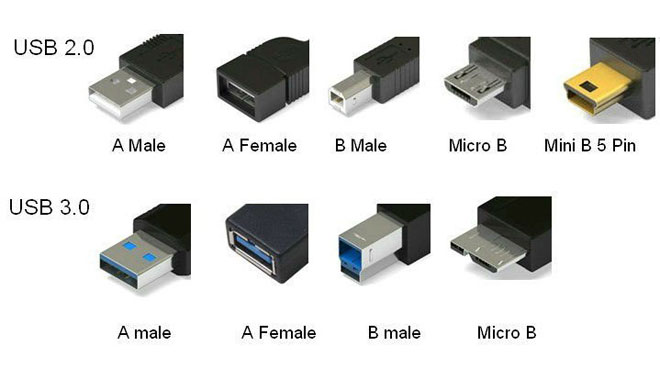
Despite the fact that the serial bus is called universal, it is represented by 2 types. They perform different functions and provide compatibility with devices with improved performance.
Type A includes active, powered devices (computer, host), to type B - passive, connected equipment (printer, scanner). All sockets and plugs of Gen 2 and Rev 3.0 Type A busbars are designed to work together. The 3rd generation bus connector type B is larger than the version 2.0 type B plug, so a device with a universal bus 2.0 type B connector is connected using only a USB 2.0 cable. Connecting external equipment with 3.0 type B connectors is done with both types of cables.
Classic type B connectors are not suitable for connecting small electronic equipment. Connection of tablets, digital equipment, mobile phones is carried out using miniature connectors Mini-USB and their improved modification Micro-USB. These connectors have reduced plug and socket dimensions.
The latest modification of the USB connectors is type C. This design has the same connectors at both ends of the cable, it is characterized by faster data transfer and more power.
Pinout USB 2.0 connector types A and B
Classic connectors contain 4 types of contacts, in mini- and microformats - 5 contacts. Wire colors in USB 2.0 cable:
- +5V (red VBUS), voltage 5 V, maximum current 0.5 A, designed for power supply;
- D-(white) Data-;
- D+(green) Data+;
- GND (black), voltage 0 V, is used for grounding.
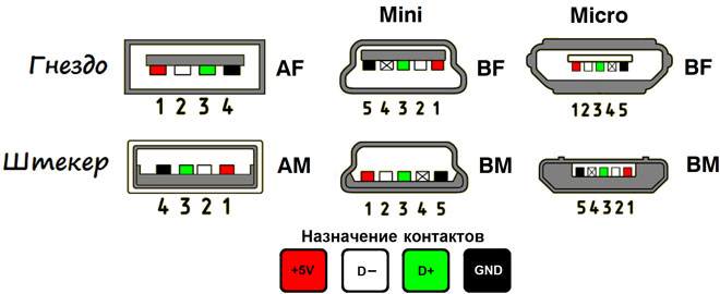
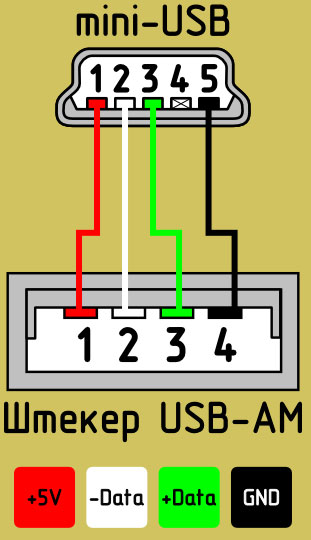
For mini format: mini-USB and micro-USB:
- Red VBUS (+), voltage 5 V, current 0.5 A.
- White (-), D-.
- Green (+), D+.
- ID - for type A they close to GND, to support the OTG function, and for type B they do not use it.
- Black GND, voltage 0V, used for ground.
Most cables have a Shield wire, it has no insulation, it is used as a shield. It is not marked and is not assigned a number. The universal bus has 2 types of connector. They have the designation M (male) and F (female). Connector M (dad) is called a plug, it is inserted, connector F (mother) is called a nest, they are inserted into it.
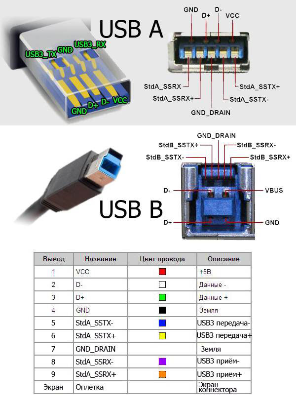
USB 3.0 pinout types A and B
Bus version 3.0 has a 10 or 9 wire connection. 9 pins is used if the Shield wire is missing. The arrangement of contacts is made in such a way that devices of earlier modifications can be connected.
USB 3.0 pinout:
- A - plug;
- B - nest;
- 1, 2, 3, 4 - contacts that match the pinout in specification 2.0 have the same color scheme;
- 5, 6 contacts for data transfer via the SUPER_SPEED protocol are designated SS_TX- and SS_TX+, respectively;
- 7 — grounding GND;
- 8, 9 - contact pads of wires for receiving data via the SUPER_SPEED protocol, pin designation: SS_RX- and SS_RX +.
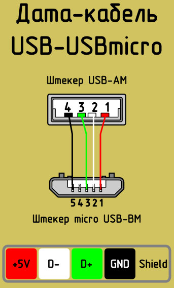
Micro USB pinout
The Micro-USB cable has 5 pad connectors. A separate mounting wire is supplied to them in the insulation of the desired color. In order for the plug to fit accurately and tightly into the socket, the upper shielding part has a special chamfer.The micro USB contacts are numbered 1 to 5 and read from right to left.
The pinouts of the micro- and mini-USB connectors are identical, presented in the table:
| wire number | Purpose | Color |
| 1 | VCC supply 5V | red |
| 2 | data | white |
| 3 | data | green |
| 4 | ID function, for type A shorted to ground | |
| 5 | grounding | black |
The shield wire is not soldered to any pin.
Mini-USB Pinout
Mini-A and Mini-B connectors appeared on the market in 2000, using the USB 2.0 standard. To date, little used due to the emergence of more advanced modifications. They were replaced by micro connectors and USB type C models. The mini connectors use 4 shielded wires and an ID function. 2 wires are used for power: supply +5 V and ground GND. 2 wires for receiving and sending differential data signals, designated D+ and D-pin. Data+ and Data- signals are transmitted via twisted pair. D+ and D- always work together, they are not separate simplex connections.
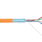
USB connectors use 2 types of cables:
- shielded, 28 AWG stranded, rated at 28 AWG or 20 AWG without twist;
- unshielded, 28 AWG without twist, 28 AWG or 20 AWG without twist.
The length of the cable depends on the power:
- 28 - 0.81 m;
- 26 - 1.31 m;
- 24 - 2.08 m;
- 22 - 3.33 m;
- 20 - 5 m.
Many manufacturers of digital equipment develop and complete their products with connectors of a different configuration. This can make it difficult to charge your mobile phone or other devices.
Similar articles: