In the material, we will understand the concept of EMF induction in situations of its occurrence. We also consider inductance as a key parameter for the occurrence of a magnetic flux when an electric field appears in a conductor.
Electromagnetic induction is the generation of electric current by magnetic fields that change over time. Thanks to the discoveries of Faraday and Lenz, patterns were formulated into laws, which introduced symmetry into the understanding of electromagnetic flows. Maxwell's theory brought together knowledge about electric current and magnetic fluxes. Thanks to the discovery of Hertz, humanity learned about telecommunications.
Content
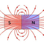
magnetic flux
An electromagnetic field appears around a conductor with an electric current, however, in parallel, the opposite phenomenon also occurs - electromagnetic induction.Consider the magnetic flux as an example: if a conductor frame is placed in an electric field with induction and moved from top to bottom along magnetic field lines or to the right or left perpendicular to them, then the magnetic flux passing through the frame will be constant.
When the frame rotates around its axis, then after a while the magnetic flux will change by a certain amount. As a result, an EMF of induction arises in the frame and an electric current appears, which is called induction.
EMF induction
Let us examine in detail what the concept of EMF of induction is. When a conductor is placed in a magnetic field and it moves with the intersection of the field lines, an electromotive force appears in the conductor called the induction EMF. It also occurs if the conductor remains stationary, and the magnetic field moves and intersects with the conductor lines of force.
When the conductor, where the emf occurs, closes to the external circuit, due to the presence of this emf, an induction current begins to flow through the circuit. Electromagnetic induction involves the phenomenon of EMF induction in a conductor at the moment it is crossed by magnetic field lines.
Electromagnetic induction is the reverse process of transforming mechanical energy into electric current. This concept and its laws are widely used in electrical engineering, most electric machines are based on this phenomenon.
Faraday and Lenz laws
The laws of Faraday and Lenz reflect the patterns of occurrence of electromagnetic induction.
Faraday found that magnetic effects appear as a result of changes in the magnetic flux over time.At the moment of crossing the conductor with an alternating magnetic current, an electromotive force arises in it, which leads to the appearance of an electric current. Both a permanent magnet and an electromagnet can generate current.
The scientist determined that the intensity of the current increases with a rapid change in the number of lines of force that cross the circuit. That is, the EMF of electromagnetic induction is in direct proportion to the speed of the magnetic flux.
According to Faraday's law, the induction EMF formulas are defined as follows:
E \u003d - dF / dt.
The minus sign indicates the relationship between the polarity of the induced EMF, the direction of the flow, and the changing speed.
According to Lenz's law, it is possible to characterize the electromotive force depending on its direction. Any change in the magnetic flux in the coil leads to the appearance of an EMF of induction, and with a rapid change, an increasing EMF is observed.
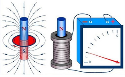
If the coil, where there is an EMF of induction, has a short circuit to an external circuit, then an induction current flows through it, as a result of which a magnetic field appears around the conductor and the coil acquires the properties of a solenoid. As a result, a magnetic field is formed around the coil.
E.Kh. Lenz established a pattern according to which the direction of the induction current in the coil and the induction EMF are determined. The law states that the induction EMF in the coil, when the magnetic flux changes, forms a directional current in the coil, in which the given magnetic flux of the coil makes it possible to avoid changes in the extraneous magnetic flux.
Lenz's law applies to all situations of electric current induction in conductors, regardless of their configuration and the method of changing the external magnetic field.
The movement of a wire in a magnetic field
The value of the induced EMF is determined depending on the length of the conductor crossed by the field lines of force. With a larger number of field lines, the value of the induced emf increases. With an increase in the magnetic field and induction, a greater value of EMF occurs in the conductor. Thus, the value of the EMF of induction in a conductor moving in a magnetic field is directly dependent on the induction of the magnetic field, the length of the conductor and the speed of its movement.
This dependence is reflected in the formula E = Blv, where E is the induction emf; B is the value of magnetic induction; I is the length of the conductor; v is the speed of its movement.
Note that in a conductor that moves in a magnetic field, the induction EMF appears only when it crosses the magnetic field lines. If the conductor moves along the lines of force, then no EMF is induced. For this reason, the formula applies only in cases where the movement of the conductor is directed perpendicular to the lines of force.
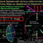
The direction of the induced EMF and electric current in the conductor is determined by the direction of movement of the conductor itself. To identify the direction, the right hand rule has been developed. If you hold the palm of your right hand so that the field lines enter in its direction, and the thumb indicates the direction of movement of the conductor, then the remaining four fingers indicate the direction of the induced emf and the direction of the electric current in the conductor.
Rotating coil
The functioning of the electric current generator is based on the rotation of the coil in a magnetic flux, where there is a certain number of turns. EMF is induced in an electric circuit always when it is crossed by a magnetic flux, based on the magnetic flux formula Ф \u003d B x S x cos α (magnetic induction multiplied by the surface area through which the magnetic flux passes, and the cosine of the angle formed by the direction vector and the perpendicular plane lines).
According to the formula, F is affected by changes in situations:
- when the magnetic flux changes, the direction vector changes;
- the area enclosed in the contour changes;
- angle changes.
It is allowed to induce EMF with a stationary magnet or a constant current, but simply when the coil rotates around its axis within the magnetic field. In this case, the magnetic flux changes as the angle changes. The coil in the process of rotation crosses the lines of force of the magnetic flux, as a result, an EMF appears. With uniform rotation, a periodic change in the magnetic flux occurs. Also, the number of field lines that intersect every second becomes equal to the values at regular intervals.
In practice, in alternating electric current generators, the coil remains stationary, and the electromagnet rotates around it.
EMF self-induction
When an alternating electric current passes through the coil, an alternating magnetic field is generated, which is characterized by a changing magnetic flux that induces an EMF. This phenomenon is called self-induction.
Due to the fact that the magnetic flux is proportional to the intensity of the electric current, then the self-induction EMF formula looks like this:
Ф = L x I, where L is the inductance, which is measured in H.Its value is determined by the number of turns per unit length and the value of their cross section.
Mutual induction
When two coils are located side by side, they observe the EMF of mutual induction, which is determined by the configuration of the two circuits and their mutual orientation. With increasing separation of the circuits, the value of mutual inductance decreases, since there is a decrease in the total magnetic flux for the two coils.
Let us consider in detail the process of the emergence of mutual induction. There are two coils, current I1 flows through the wire of one with N1 turns, which creates a magnetic flux and goes through the second coil with N2 number of turns.
The value of the mutual inductance of the second coil in relation to the first:
M21 = (N2 x F21)/I1.
Magnetic flux value:
F21 = (M21/N2) x I1.
The induced emf is calculated by the formula:
E2 = - N2 x dФ21/dt = - M21x dI1/dt.
In the first coil, the value of the induced emf:
E1 = - M12 x dI2/dt.
It is important to note that the electromotive force provoked by mutual induction in one of the coils is in any case directly proportional to the change in electric current in the other coil.
Then the mutual inductance is considered equal to:
M12 = M21 = M.
As a consequence, E1 = - M x dI2/dt and E2 = M x dI1/dt. M = K √ (L1 x L2), where K is the coupling coefficient between the two inductance values.
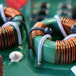
Mutual inductance is widely used in transformers, which make it possible to change the value of an alternating electric current. The device is a pair of coils that are wound on a common core. The current in the first coil forms a changing magnetic flux in the magnetic circuit and a current in the second coil.With fewer turns in the first coil than in the second, the voltage increases, and accordingly, with a larger number of turns in the first winding, the voltage decreases.
In addition to generating and transforming electrical energy, the phenomenon of magnetic induction is used in other devices. For example, in magnetic levitation trains moving without direct contact with the current in the rails, but a couple of centimeters higher due to electromagnetic repulsion.
Similar articles: