An oscilloscope is a device that demonstrates the current strength, voltage, frequency and phase shift of an electrical circuit. The device displays the ratio of time and intensity of the electrical signal. All values are shown using a simple two-dimensional graph.
Content
What is an oscilloscope for?
An oscilloscope is used by electronics and radio amateurs to measure:
- the amplitude of the electrical signal - the ratio of voltage and time;
- analyze the phase shift;
- see the distortion of the electrical signal;
- based on the results, calculate the frequency of the current.
Despite the fact that the oscilloscope demonstrates the characteristics of the analyzed signal, it is more often used to identify processes occurring in an electrical circuit.Thanks to the oscillogram, specialists receive the following information:
- shape of a periodic signal;
- value of positive and negative polarity;
- range of signal change in time;
- the duration of the positive and negative half-cycle.
Most of this information can be obtained with a voltmeter. However, then you will have to make measurements with a frequency of several seconds. At the same time, the percentage of calculation errors is large. Working with an oscilloscope saves a lot of time in obtaining the necessary data.
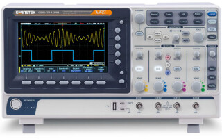
The principle of operation of the oscilloscope
An oscilloscope takes measurements using a cathode ray tube. This is a lamp that focuses the analyzed current into a beam. It hits the screen of the device, deviating in two perpendicular directions:
- vertical - shows the voltage under study;
- horizontal - shows the elapsed time.
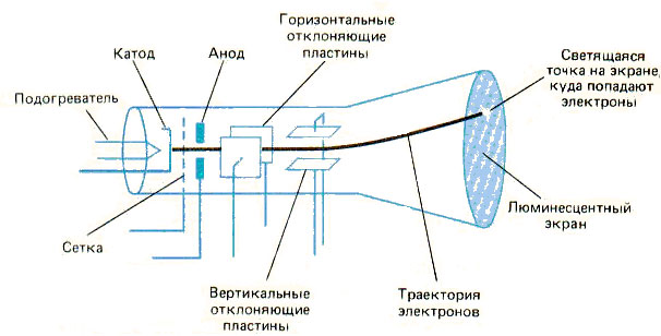
Two pairs of cathode ray tube plates are responsible for deflecting the beam. Those that are located vertically are always energized. This helps to distribute the polarity values. Positive attraction deviates to the right, negative attraction deviates to the left. Thus, the line on the instrument screen moves from left to right at a constant speed.
An electric current also acts on the horizontal plates, which deflects the beam voltage indicator. Positive charge is up, negative charge is down. So on the display of the device appears a linear two-dimensional graph, which is called an oscillogram.
The distance that the beam travels from the left to the right edge of the screen is called the sweep. The horizontal line is responsible for the measurement time.In addition to the standard 2D line graph, there are also circular and spiral sweeps. However, using them is not as convenient as classic oscillograms.
Classification and types
There are two main types of oscilloscopes:
- analog - devices for measuring average signals;
- digital - devices convert the received measurement value into a "digital" format for further transmission of information.
According to the principle of action, there is the following classification:
- Universal models.
- Special equipment.
most popular are universal devices. These oscilloscopes are used to analyze various types of signals:
- harmonic;
- single impulses;
- impulse packs.
Universal devices are designed for a variety of electrical devices. They allow you to measure signals in the range of a few nanoseconds. The measurement error is 6-8%.
Universal oscilloscopes are divided into two main types:
- monoblock - have a common measurement specialization;
- with interchangeable blocks - adapt to a specific situation and type of device.
Special devices are developed for a certain type of electrical equipment. So there are oscilloscopes for radio signal, television broadcasting or digital technology.
Universal and special devices are divided into:
- high-speed - used in high-speed devices;
- memory - devices that store and reproduce previously made indicators.
When choosing a device, you should carefully study the classifications and types in order to purchase a device for a specific situation.
Device and main technical parameters
Each device has a number of the following technical characteristics:
- The coefficient of possible error when measuring voltage (for most devices, this value does not exceed 3%).
- The value of the device baseline - the larger this characteristic, the longer the time period of observation.
- Synchronization characteristic, containing: frequency range, maximum levels and system instability.
- Parameters of the vertical deviation of the signal with the input capacitance of the equipment.
- Step response values showing rise time and overshoot.
In addition to the basic values listed above, oscilloscopes have additional parameters, in the form of an amplitude-frequency characteristic, which demonstrates the dependence of the amplitude on the signal frequency.
Digital oscilloscopes also have a lot of internal memory. This parameter is responsible for the amount of information that the device can record.
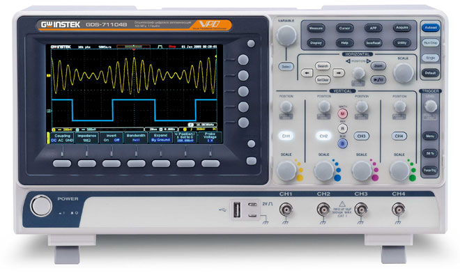
How measurements are taken
The oscilloscope screen is divided into small cells called divisions. Depending on the device, each square will be equal to a certain value. The most popular designation: one division - 5 units. Also, on some devices there is a knob for controlling the scale of the graph, so that it is more convenient and more accurate for users to make measurements.
Before you start any kind of measurement, you must connect the oscilloscope to the electrical circuit. The probe is connected to any of the free channels (if the device has more than 1 channel) or to the pulse generator, if available in the device. After connection, various signal images will appear on the display of the unit.
If the signal received by the device is intermittent, then the problem lies in the connection of the probe. Some of them are equipped with miniature screws that need to be tightened. Also in digital oscilloscopes, the automatic positioning fiction solves the problem of an intermittent signal.
Current measurement
When measuring current with a digital oscilloscope, you should find out which type of current needs to be observed. Oscilloscopes have two modes of operation:
- Direct Current ("DC") for direct current;
- Alternating Current ("AC") for variable.
Direct current is measured with the "Direct Current" mode enabled. The probes of the device should be connected to the power supply in direct accordance with the poles. The black crocodile joins the minus, the red crocodile joins the plus.
A straight line will appear on the screen of the device. The value of the vertical axis will correspond to the constant voltage parameter. The current strength can be calculated according to Ohm's law (voltage divided by resistance).
Alternating current is a sinusoid, due to the fact that the voltage is also variable. Therefore, its value can be measured only in a certain period of time. The parameter is also calculated using Ohm's law.
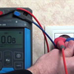
Voltage measurement
To measure the voltage of a signal, you need the vertical coordinate axis of a linear two-dimensional graph. Because of this, all attention will be paid to the height of the waveform. Therefore, before starting the observation, you should adjust the screen more conveniently for measurement.
Then we transfer the device to DC mode. We attach the probes to the circuit and observe the result. A straight line will appear on the display of the device, the value of which will correspond to the voltage of the electrical signal.
Frequency measurement
Before you understand how to measure the frequency of an electrical signal, you should know what a period is, since these two concepts are interrelated. One period is the smallest period of time after which the amplitude begins to repeat.
It is easier to see the period on the oscilloscope using the horizontal time axis. It is only necessary to notice after what period of time the line chart begins to repeat its pattern. It is better to consider the beginning of the period as the points of contact with the horizontal axis, and the end of the repetition of the same coordinate.
To more conveniently measure the period of the signal, the sweep speed is reduced. In this case, the measurement error is not so high.
Frequency is a value inversely proportional to the analyzed period. That is, to measure the value, you need to divide one second of time by the number of periods occurring during this period. The resulting frequency is measured in Hertz, the standard for Russia is 50 Hz.
Phase shift measurement
Phase shift is considered - the relative position of two oscillatory processes in time. The parameter is measured in fractions of the signal period, so that, regardless of the nature of the period and frequency, the same phase shifts have a common value.
The first thing to do before the measurement is to find out which of the signals lags behind the other and then determine the sign value of the parameter. If the current is leading, then the angle shift parameter is negative. In the case when the voltage is ahead, the sign of the value is positive.
To calculate the degree of phase shift, you should:
- Multiply 360 degrees by the number of grid cells between the beginning of the periods.
- Divide the result by the number of divisions occupied by one signal period.
- Pick a negative or positive sign.
It is inconvenient to measure the phase shift in an analog oscilloscope, because the graphs displayed on the screens have the same color and scale. For observations of this kind, either a digital device or two-channel devices are used to place different amplitudes on a separate channel.
Similar articles: