Current transformers are widely used in modern energy as equipment for changing various electrical parameters into similar ones while maintaining the basic values. The operation of the equipment is based on the law of induction, which is relevant for magnetic and electric fields that change sinusoidally. The transformer transforms the primary value of the current in compliance with the modulus and the transmission of the angle in proportion to the original data. It is required to choose equipment based on the scope of use of the devices and the number of connected consumers.
Content
What is a current transformer?
This equipment is used in industry, urban communications and engineering networks, in production and in other areas to supply current with certain physical parameters.Voltage is applied to the turns of the primary winding, where, as a result of magnetic radiation, an alternating current is formed. The same radiation passes through the remaining turns, due to which the EMF forces move, and when the secondary turns are shorted or when connected to an electrical circuit, a secondary current appears in the system.
Modern current transformers allow you to convert energy with such parameters that its use does not allow harm to the equipment that works on it. In addition, they make it possible to measure increased loads with maximum safety for equipment and personnel, since the turns of the primary and secondary rows are reliably isolated from each other.
Purpose of transformers
It is quite simple to determine why a current transformer is needed: the scope includes all industries in which energy quantities are converted. These devices are among the auxiliary equipment that is used in parallel with measuring instruments and relays when creating an AC circuit. In these cases, transformers convert energy for more convenient decoding of parameters or connecting equipment with different characteristics into one circuit.
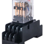
They also distinguish the measuring function of transformers: they serve to start electrical circuits with increased voltage, to which it is required to connect measuring instruments, but it is not possible to do this directly. The main task of such transformers is to transfer the received information about the current parameters to the instruments for measuring manipulations, which are connected to the secondary type winding.The equipment also makes it possible to control the current in the circuit: when using a relay and reaching the maximum current parameters, protection is activated that turns off the equipment in order to avoid burnout and harm to personnel.
Principle of operation
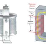
The operation of such equipment is based on the law of induction, according to which voltage enters the primary turns and the current overcomes the winding resistance created, which causes the formation of a magnetic flux transmitted to the magnetic circuit. The flow goes in a perpendicular direction relative to the current, which minimizes losses, and when it crosses the turns of the secondary winding, the EMF force is activated. As a result of its influence, a current appears in the system, which is stronger than the resistance of the coil, while the voltage at the output of the secondary turns decreases.
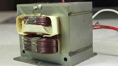
The simplest design of a transformer thus consists of a core of metal and a pair of windings not connected to each other and made as wire with insulation. In some cases, the load goes only to the primary, and not the secondary turns: this is the so-called idle mode. If, on the other hand, equipment that consumes energy is connected to the secondary winding, a current passes through the turns, which creates an electromotive force. The EMF parameters are determined by the number of turns. The ratio of the electromotive force for the primary and secondary turns is known as the transformation ratio, calculated from the ratio of their number. It is possible to regulate the voltage for the final consumer of energy by changing the number of turns of the primary or secondary winding.
Classification of current transformers
There are several types of such equipment, which are divided according to a number of criteria, including purpose, installation method, number of conversion stages, and other factors. Before choosing a current transformer, you need to consider these parameters:
- Appointment. According to this criterion, measuring, intermediate and protecting models are distinguished. So, devices of an intermediate type are used when connecting devices for computing actions in relay protection systems and other circuits. Separately, laboratory transformers are distinguished, which provide increased accuracy of indicators, have a large number of conversion factors.
- Installation method. There are transformers for external and internal installation: they not only look different, but also have different indicators of resistance to external influences (for example, devices for outdoor use are protected from precipitation and temperature changes). Overhead and portable transformers are also distinguished; the latter have a relatively small mass and dimensions.
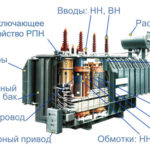
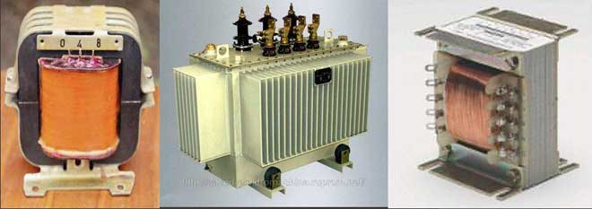
- Winding type. Transformers are single- and multi-turn, coil, rod, busbar. Both the primary and secondary windings can differ, and the differences also relate to insulation (dry, porcelain, bakelite, oil, compound, etc.).
- The level of transformation steps. The equipment can be one- and two-stage (cascade), the voltage limit of 1000 V can be minimal or, on the contrary, maximum.
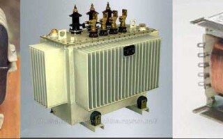
- Design. According to this criterion, two types of current transformers are distinguished - oil and dry.In the first case, the winding turns and the magnetic circuit are in a container containing a special oily liquid: it plays the role of insulation and allows you to control the operating temperature of the medium. In the second case, cooling occurs by air, such systems are used in industrial and residential buildings, since oil transformers cannot be installed inside due to increased fire hazard.
- Voltage type. Transformers can be step-down and step-up: in the first case, the voltage on the primary turns is reduced, and in the second, it is increased.
- Another classification option is the choice of current transformer by power. This parameter depends on the purpose of the equipment, the number of connected consumers, their properties.
Parameters and characteristics
When choosing such equipment, it is necessary to take into account the main technical parameters that affect the range of applications and cost. Main qualities:
- Rated load, or power: selection by this criterion can be done using a comparative table of transformer characteristics. The parameter value determines other current characteristics, since it is strictly normalized and serves to determine the normal operation of the equipment in the selected accuracy class.
- Rated current. This indicator determines the period during which the device can function without overheating to critical temperatures. In transformer equipment, as a rule, there is a solid reserve in terms of the level of heating, with an overload of up to 18-20%, operation occurs in normal mode.
- Voltage.The indicator is important for the quality of the winding insulation, ensures the smooth operation of the equipment.
- Error. This phenomenon occurs due to the influence of magnetic flux, the error rate is the difference between the exact data of the primary and secondary current. The increase in the magnetic flux in the transformer core contributes to a proportional increase in the error.
- The transformation ratio, which is the ratio of current in the primary and secondary turns. The real value of the coefficient differs from the nominal value by an amount equal to the degree of losses during energy conversion.
- The limiting multiplicity, expressed in relation to the primary current in real form to the nominal value.
- The multiplicity of the current that occurs in the turns of the secondary type winding.
The key data of the current transformer are determined by the equivalent circuit: it allows you to study the characteristics of the equipment in different modes, from idle to full load.
The main indicators are indicated on the body of the device in the form of a special marking. It may also contain data on the method of lifting and mounting equipment, warning information about increased voltage on the secondary turns (over 350 Volts), information about the presence of a grounding pad. The marking of the energy converter is applied in the form of a sticker or with paint.
Possible malfunctions
Like any other equipment, transformers break down from time to time, and they require qualified service with diagnostics. Before checking the device, you need to know what breakdowns are, what signs correspond to them:
- Uneven noise inside the case, crackling.This phenomenon usually indicates a break in the grounding element, an overlap on the case from the winding turns, or a weakening of the pressing of the sheets used for the magnetic circuit.
- Too much heating of the case, increase in current strength on the consumption side. The problem can be caused by a winding short circuit due to wear or mechanical damage to the insulating layer, frequent overloads resulting from a short circuit.
- Cracks in insulators, sliding discharges. They appear when a manufacturing defect was not identified before the start of operation, a cast of foreign objects and an overlap between the input of phases of different values.
- Oil emissions during which the membrane of the exhaust structure is destroyed. The problem is explained by an interfacial short circuit due to insulation wear, a decrease in the oil level, voltage drops or the appearance of overcurrents under the condition of a through-type short circuit.
- Oil leaks from gaskets or transformer taps. The main reasons are poor-quality welding of nodes, poor sealing, destruction of gaskets or non-lapped valve plugs.
- Switching on the gas protection relay. This phenomenon occurs when the oil decomposes, which occurs due to a winding short circuit, an open circuit, burnout of the contacts of the switching device, or in the event of a short circuit to the transformer housing.
- Switching off the gas protection relay. The problem is caused by the active decomposition of the oily liquid as a result of interfacial closure, overvoltage of the internal or external part, or due to the so-called "steel fire".
- Tripped differential protection. This malfunction appears when there is a breakdown on the inlet housing, when there is an overlap between phases, or in other cases.
To maximize the efficiency of the device functionality, it is necessary to regularly perform verification using a thermal imager: the equipment allows diagnosing a decrease in the quality of contacts and a decrease in operating temperature. During verification, specialists perform the following range of manipulations:
- Taking voltage and current readings.
- Checking the load using an external source.
- Determination of parameters in the working scheme.
- Calculation of the transformation ratio, comparison and analysis of indicators.
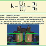
Calculation of the transformer
The basic principle of operation of this device is determined by the formula U1/U2=n1/n2, the elements of which are decoded as follows:
- U1 and U2 are the voltage of the primary and secondary turns.
- n1 and n2 - their number on the windings of the primary and secondary types, respectively.
To determine the cross-sectional area of \u200b\u200bthe core, another formula is used: S=1.15*√P, in which power is measured in watts, and area is measured in square centimeters. If the core used in the equipment has the shape of the letter W, the section index is calculated for the middle rod. When determining the turns in the winding of the primary level, the formula is used n=50*U1/S, while component 50 is not immutable, in calculations to prevent the occurrence of electromagnetic interference, it is recommended to set the value 60 instead of it. Another formula is d=0.8*√I, in which d is the cross section of the wire, and I is the current strength indicator; it is used to calculate the cable diameter.
The figures obtained during the calculations are adjusted to round values (for example, the estimated power of 37.5 W is rounded up to 40). Rounding is allowed only up.All of these formulas are used to select transformers operating in a 220 Volt network; when constructing high-frequency lines, other parameters and calculation methods are used.
Similar articles: