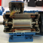
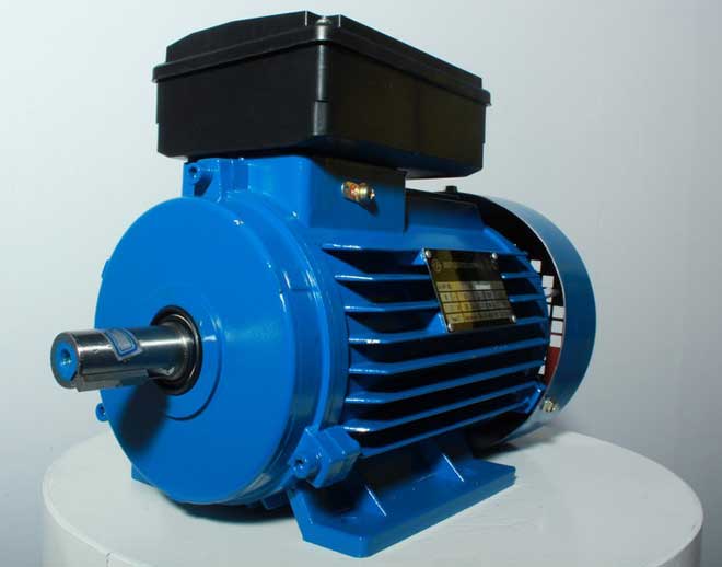
The functioning of a single-phase electric motor is based on the use of alternating electric current by connecting to single-phase networks. The voltage in such a network must correspond to the standard value of 220 Volts, the frequency is 50 Hertz. Motors of this type are mainly used in household appliances, pumps, small fans, etc.
The power of single-phase motors is also sufficient for the electrification of private houses, garages or summer cottages. Under these conditions, a single-phase electrical network with a voltage of 220 V is used, which imposes some requirements on the process of connecting the motor. A special circuit is used here, involving the use of a device with a starting winding.
Content
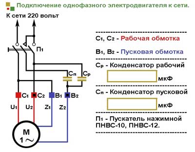
Scheme of connecting a single-phase motor through a capacitor
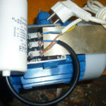
Single-phase 220v electric motors are connected to the network using a capacitor. This is due to some design features of the unit.So, on the motor stator, an alternating current winding creates a magnetic field, the impulses of which are compensated only if the polarity is reversed at a frequency of 50 Hz. Despite the characteristic sounds that a single-phase motor makes, the rotation of the rotor does not occur. Torque is generated through the use of additional starting windings.
To understand how to connect a single-phase electric motor through a capacitor, it is enough to consider 3 working circuits using a capacitor:
- launcher;
- working;
- running and starting (combined).
Each of the listed connection schemes is suitable for use in the operation of 220v asynchronous single-phase electric motors. However, each option has its strengths and weaknesses, so they deserve a closer look.
The idea of using a starting capacitor is to include it in the circuit only at the moment the motor starts. To do this, the circuit provides for the presence of a special button designed to open the contacts after the rotor reaches a given speed level. Its further rotation occurs under the influence of inertial force.
Maintenance of rotational movements over a long period of time is provided by the magnetic field of the main winding of a single-phase motor with a capacitor. In this case, the functions of the switch can be performed by a specially provided relay.
The connection diagram of a single-phase electric motor through a capacitor assumes the presence of a pressure spring button that breaks the contacts at the moment of opening.This approach makes it possible to reduce the number of wires used (the use of a thinner starting winding is allowed). To avoid the occurrence of short circuits between the turns, it is recommended to use a thermal relay.
When critically high temperatures are reached, this element deactivates the additional winding. A similar function can be performed by a centrifugal switch installed to open the contacts in cases where the permissible values of the rotation speed are exceeded.
To automatically control the speed of rotation and protect the motor from overloads, appropriate schemes are developed, and various corrective components are introduced into the design of the units. The installation of the centrifugal switch can be done directly on the rotor shaft or on elements associated with it (direct or geared connection).
The centrifugal force acting on the load contributes to the tension of the spring connected to the contact plate. If the rotation speed reaches the set value, the contacts close, the current supply to the motor stops. It is possible to transmit a signal to another control mechanism.
There are variants of schemes in which the presence of a centrifugal switch and a thermal relay is provided in one structural element. This solution makes it possible to deactivate the motor by means of a thermal component (in case of reaching critical temperatures) or under the influence of the sliding element of the centrifugal switch.
In the case of connecting the motor through a capacitor, there is often a distortion of the magnetic field lines in the additional winding. This entails an increase in power losses, a general decrease in the performance of the unit.However, good start-up performance is maintained.
The use of a working capacitor in the circuit for connecting a single-phase motor with a starting winding suggests a number of distinctive features. So, after starting, the capacitor does not turn off, the rotation of the rotor is carried out due to the impulse action from the secondary winding. This significantly increases the power of the engine, and a competent selection of the capacitance of the capacitor allows you to optimize the shape of the electromagnetic field. However, starting the engine becomes longer.
The selection of a capacitor of suitable power is carried out taking into account current loads, which allows optimizing the electromagnetic field. In the event of a change in the nominal values, there will be fluctuation in all other parameters. To stabilize the shape of the lines of magnetic fields allows the use of several capacitors with different capacitance characteristics. This approach allows you to optimize the performance of the system, but involves some difficulties in the installation and operation processes.
The combined circuit for connecting a single-phase motor with a starting winding is designed to use two capacitors - working and starting. This is the optimal solution for medium performance.
Motor Capacitor Calculation
There is a complex formula by which the required exact capacitance of a capacitor is calculated. However, many years of experience of professionals shows that it is enough to adhere to the following recommendations:
- for 1 kW of motor power, 0.8 μF of a working capacitor is required;
- the starting winding requires this value to be 2 or 3 times higher.
The operating voltage for them should be 1.5 times higher than in the mains (in our case, 220 V). To simplify the starting process, it is better to install a capacitor marked "Starting" or "Start" in the starting circuit. Although the use of standard capacitors is allowed.
Motor direction reversal
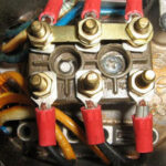
It is possible that after connection, single-phase electric motors will rotate in the opposite direction to that required. It's easy to fix. During the assembly of the circuit, one wire was brought out as a common one, another conductor was fed to the button. In order to change the rotating magnetic direction of the electric motor, these 2 wires must be reversed.
Similar articles: