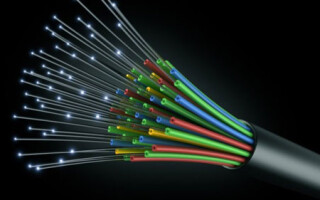
Fiber optic cables are widely used today for data transmission. In some areas of IT, they have completely replaced traditional communication lines based on metal conductors. Optical lines are especially effective where large amounts of data must be transmitted over long distances.
Content
The physical basis of fiber optics
The physical principles of optical fiber operation are based on the principle of total reflection. If we take two media with different refractive indices n1 and n2, and n2<n1 (for example, air and glass or glass and transparent plastic) and let a beam of light at an angle α to the interface, then two events will occur.
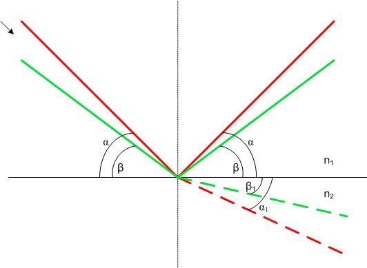
A beam (indicated in red in the figure), launched from the top left (along the arrow), will be partially refracted and will go through a medium with a refractive index n2 angle α1<α - this part of the beam is indicated by a dashed line.The other part of the beam will be reflected from the interface at the same angle. If the beam is fired at a shallower angle β (the green beam in the figure), then the same thing will happen - partial reflection and partial refraction at an angle β1.
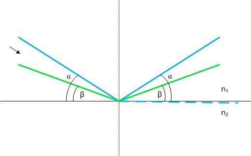
If the angle of incidence α is further reduced (blue beam in the figure), then the refracted part of the beam can “slide” almost parallel to the media interface (blue dashed line). A further decrease in the angle of incidence (a green beam incident at an angle β) will cause a qualitative jump - the refracted part will be absent. The beam will be completely reflected from the interface between the two media. This angle is called the angle of total reflection, and the phenomenon itself is called total reflection. The same will be observed with a further decrease in the angle of incidence.
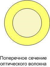
Optical fiber device
Optical fiber is built on this principle. It consists of two coaxial layers with different optical density.
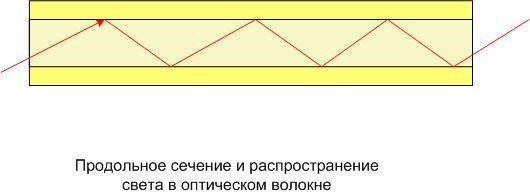
If a light beam enters the open end of the fiber at an angle greater than the angle of light reflection, it will be completely reflected from the contact boundary of two media with different refractive indices, with low attenuation at each "jump".
The outer part of the optical fiber is made of plastic. The inner one can also be made of transparent plastic, then it can be bent at sufficiently large angles (even rolled into a ring, and the light that gets inside will still pass from one end to the other with attenuation depending on the optical properties of the plastic and the length of the light guide). For backbone cables where flexibility is not as important, the inner core is usually made of glass.This reduces the attenuation, reduces the cost of the fiber, but it becomes sensitive to bends.
To increase the throughput of an optical line, the fiber is produced in a two-mode or multi-mode version. To do this, the core cross section is increased to 50 microns or 62.5 microns (versus 10 microns for single-mode). Two or more signals can be simultaneously transmitted through such an optical fiber.
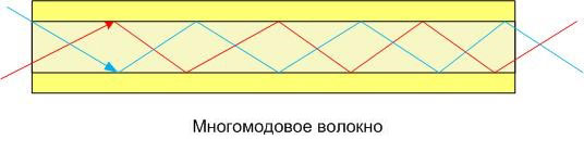 This construction of the optical transmission line has certain disadvantages. One of them is the light dispersion caused by the different path of each signal. They learned to deal with it by making a core with a gradient (changing from the middle to the edges) refractive index. Due to this, the routes of different beams are corrected.
Cables with multimode fibers are mainly used for local networks (within the same building, one enterprise, etc.), and with single-mode fibers - for trunk lines.
Fiber line device
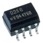
The FOCL transmits a light signal generated by an LED or a laser. An electrical signal is generated in the transmitter. The end device also needs a signal in the form of electrical impulses. Therefore, it will be necessary to transform the original data twice. A simplified diagram of a fiber optic line is shown in the figure.
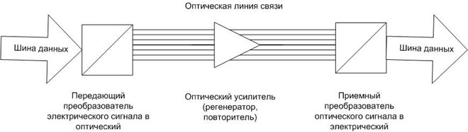
The signal from the transmitter is converted into light pulses and transmitted over an optical line. The power of the emitters on the transmitting side is limited, therefore, on long lines at certain intervals, devices are installed that compensate for attenuation - optical amplifiers, regenerators or repeaters.On the receiving side there is another converter that transforms the optical signal into an electrical one.
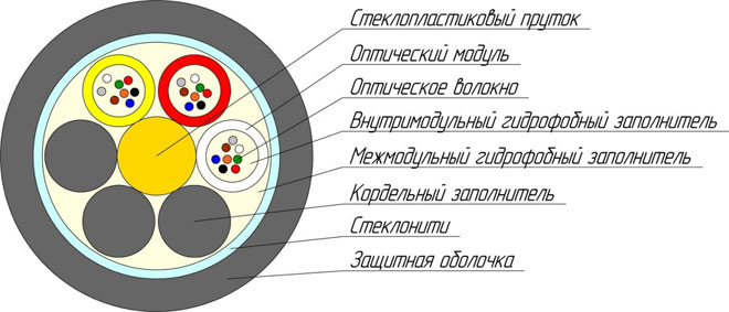
Optical cable design
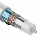
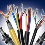
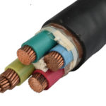
To organize a fiber-optic line, individual fibers are used as part of an optical cable. Its design depends on the purpose of the transmission line and the laying method, but in general it contains several fibers with an individual protective coating (from scratches and mechanical damage). Such protection is usually performed in two layers - first, a compound shell, and on top - an additional coating of plastic or varnish. The fibers are enclosed in a common sheath (like conventional electrical cables), which determines the scope of the cable and is selected taking into account the external influences that the line will be exposed to during operation.
When laying in cable trays, there is a problem of protecting the lines from rodents. In this case, it is necessary to choose a cable whose outer sheath is reinforced with steel tape or wire armor. Glass fibers are also used as protection against damage.
If the cable is laid in a pipe, a reinforced sheath is not needed. The metal tube reliably protects against the teeth of mice and rats. The outer shell can be made lightweight. This makes it easier to tighten the cable inside the pipe.
If a line is to be laid in the ground, protection is performed in the form of corrosion-protected wire armor or fiberglass rods. It provides high resistance not only to compression, but also to stretching.
If the cable is to be laid in sea areas, across rivers and other water barriers, on swampy soil, etc., additional protection from an aluminum polymer tape is applied. This is how water is prevented from getting in.
Also, many cables inside a common sheath contain:
- reinforcing rods that serve to give the structure greater strength under external mechanical influences and during thermal elongation of the line;
- fillers - plastic threads that fill empty areas between fibers and other elements;
- power rods (their purpose is to increase the tensile load).
In large spans, the line is suspended on a cable, but there are self-supporting cables. The supporting metal cable is built directly into the shell.
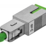
As a separate type of fiber optic line, an optical patch cord should be mentioned. This cable contains one or two fibers (single mode or dual mode) enclosed in a common sheath. On both sides, the cord is equipped with connectors for connection. Such cables are of short length and are intended for connecting equipment at a short distance or for laying intracabinet communications.
Advantages and disadvantages of optical cables
The undoubted advantages of optical cables, which determined the wide distribution of such communication lines, include:
- high noise immunity - the light signal is not affected by household and industrial electromagnetic radiation, and the line itself does not emit (this makes it difficult for unauthorized access to the transmitted information and does not create problems of electromagnetic compatibility);
- full galvanic isolation between the receiving and transmitting side;
- low attenuation level - much less than that of wired lines;
- long service life;
- large throughput.
In modern realities, it also matters that the cable does not attract metal thieves.
Optics is not without flaws. First of all, this is the complexity of installation and connection, which requires special equipment, tools and materials, and also imposes increased requirements on the qualifications of personnel involved in the installation and maintenance of lines. Most faults in FOCL are associated with installation errors, which may not manifest themselves immediately. Initially, the cost of the line itself was also high, but the development of technology has made it possible to level this disadvantage to competitive levels.
Optical communication lines have occupied a serious sector in the market of communication materials. In the foreseeable future, they do not see a serious alternative unless there is a technological breakthrough.
Similar articles: