To check the status car batteryand it is not necessary to have professional equipment, industrial stands, etc. All necessary and sufficient information for the car owner can be obtained using a multimeter and a few additional items that can be found in the garage or auto shop.
Content
Battery level
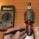
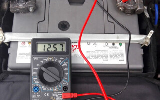
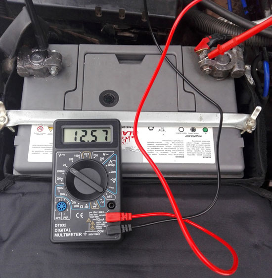
Using a tester in voltmeter mode, you can check how charged the battery is. The level of stored energy is uniquely determined by the voltage at the battery terminals at idle:
- if the voltage is 12.6 volts or higher, the battery is charged at 100;
- 12.3 ... 12.6 volts - charge level 75%;
- 12.1 ... 12.3 volts - 50%;
- 11.8 ... 12.1 volts - 25%;
- 10.5 ... 11.8 volts - the battery is completely discharged;
- less than 10.5 volts - deep discharge.
Before checking without removing it from the car, you must disconnect the positive terminal (or better, the negative one too).
Checking the actual battery capacity
To measure such an important parameter as real battery capacity, in the kit to the multimeter you need to have only connecting wires and a load of known power (or known resistance). In this capacity, it is very convenient to use car bulbs for a voltage of 12 volts:
- they are sold in any auto shop;
- you can dial the battery to any desired power and set any discharge current.
In addition, lamps as a load stabilize the current. When the voltage at the battery terminals decreases, the filaments cool down somewhat, their resistance decreases, and the current decrease is insignificant. This improves the accuracy of the measurement. But LED devices are not suitable for these purposes - they have too little power consumption, and they will need too much. Looking for incandescent bulbs.
It should be remembered that capacity depends on the current that the battery is discharging. The declared power is declared when the battery is discharged with a current of 5% of the nominal value. It is necessary to choose the power of the lamps so as to obtain such a current. For example, for a battery with a capacity of 60 A * h, it is optimal for measurement to discharge with a current of 3 A. To do this, the power of the lamps at a voltage of 12 volts should be P = U * I = 12 * 3 = 36 watts. You can take three lamps of 12 watts or two of 18 watts, etc. There is no need to chase after accuracy - the exact capacity is still unknown, it just needs to be found out.
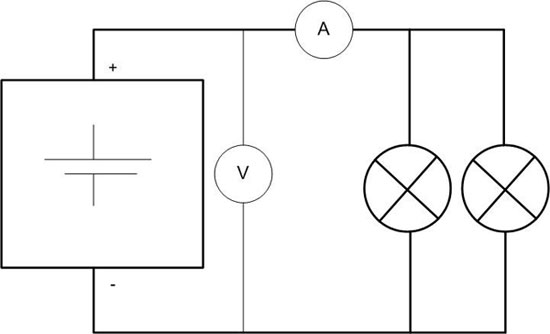
Before measuring, you must fully charge the battery and assemble the circuit as shown in the figure. The start time of the discharge must be fixed. If there are two multimeters, one can measure current, the other voltage, or you can periodically connect the tester either as a voltmeter or as an ammeter.The results should be recorded every 30-60 minutes, and when the level of 11.5 volts is reached, every 10-15 minutes. When the voltage drops to 10.5 volts, the discharge must be stopped and the time of its completion recorded. The real capacity is calculated by the formula C \u003d I * t, where:
- I - average current in amperes;
- t is the discharge time in hours.
So, if the battery was discharged for 16 hours with an average current of 3 amperes, its real capacity will be 16 * 3 = 48 A * h. Measurements must be made at a temperature of +25 °C.
Battery current measurement
Theoretically, the actual cold scroll current can be measured in this way. According to the IEC standard (to which our GOST R 53165-2008) the measurement is made at an electrolyte temperature of minus 18 degrees, with a decrease in the voltage at the terminals not lower than 8.4 volts. In practice, the problem is not only how to cool the battery to the right temperature.
For example, for a battery with a declared current output of 600 amperes, a power load of P = U * I = 8.4 * 600 = 5000 watts will be required. Now powerful light bulbs are produced mainly in LED versions, and for our purposes, as indicated above, they are of little use. If you use devices with a power of, for example, 60 watts, then in this case you will need 84 pieces.
If you wish, it is possible to assemble a large garland, but the problem of switching high currents will arise so that the contacts do not weld when the circuit is closed / opened. You can adapt for this purpose the retractor relay from the starter of the car. You will also have to find a tester with DC clamps (and such devices are less common and more expensive than variable meters) and with a measurement limit of several hundred amperes.In addition, the measurement will not last long, so you need to make sure that the multimeter has a peak-hold function.
Measuring the internal resistance of a battery
With this circuit, you can measure the internal resistance of the battery. It can be conditionally represented as a resistor connected to the battery terminals from the inside.
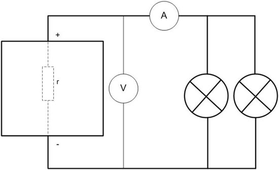
To improve accuracy, it is necessary to take a more powerful load so that the current is at least 50 amperes (and preferably 100 or more). For this, a "battery" of lamps with a total power of at least P \u003d U * I \u003d 12 * 50 \u003d 600 watts is suitable. If it turns out more, the measurement will be more accurate. Instead of lamps, you can use a resistor made, for example, from a spiral for an iron or electric stove. You just need to accurately measure its resistance. Two measurements are taken:
- at idle, fix the voltage at the battery terminals E;
- under load, measure the current I and the voltage at the terminals U.
Measurement under load is carried out once, for this a few seconds are enough. Next, you need to use Ohm's law for the complete circuit:
I=E*(R+r),
from here
r=I/E-R,
where:
- E - EMF of the battery in volts, with certain assumptions, is equal to the open circuit voltage of the battery;
- I - measured current in amperes;
- R is the resistance of the external load, Ohm.
- r is the desired internal resistance, Ohm.
The voltage at the terminals under load will allow you to calculate the load resistance (together with the connecting wires) if it is unknown (and if it is known, then when heated with high current during the experiment, it will change). It is equal to R=U/I.
The hardest part is how to interpret the result.The lower the internal resistance, the more current the battery will deliver to the load. But what kind of resistance is considered normal is not clear, because manufacturers do not indicate this value either on the battery nameplate or in the accompanying technical documentation. And there is logic to this, because internal resistance is a highly non-linear function of many things:
- temperature;
- electrolyte composition;
- the degree of charge of the battery;
- other factors.
It is difficult to comply with these conditions in the garage and even in production. You can only focus on a value of a few milliohms for a new battery with good current output. Or accumulate statistics by measuring many batteries of the same type, whose condition is known.
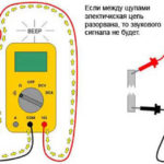
A similar measurement is made using a load fork. Only with such testing, the internal resistance is not calculated, and based on the results of two measurements (with an open circuit and under load), a conclusion is drawn from the table about the battery's performance.
Checking the operating mode as part of the electrical equipment of the car
Also, a multimeter is useful to check the operation of the battery "on board". First of all, you can determine if the battery is charging while the generator is running.
To do this, the condition that the on-board network voltage exceeds the battery voltage must be met, in which case the current will “flow” into the battery. First you need to measure the voltage at the battery terminals with the engine off. It should be between 10.5 and 12.6 volts (depending on the charge level of the battery). Then you need to start the engine, with a normally working generator, the voltage should rise to at least 14 ... 14.5 volts. If the voltage is lower, it is necessary to look for a malfunction of the generator.Both checks must be carried out with powerful consumers turned off (lighting equipment, car audio, heating devices, etc.).
Also, the tester can determine the presence of current leaks while the car is parked. To do this, it is very convenient to use a tester with DC clamps. It is necessary to turn off the engine and turn off all electrical consumers of the on-board network, as far as possible. If you measure the current along, for example, the positive wire from the battery, then the ammeter should show a value close to zero or a current similar to the consumption of loads that could not be disconnected. If the measurement result is higher, you need to look for a problem.
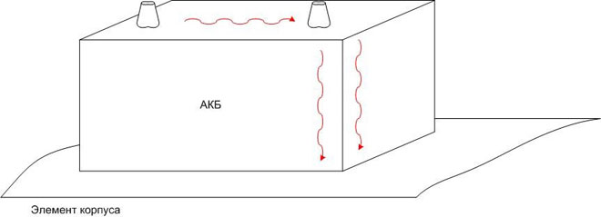
It must be remembered that if the leak goes through a layer of pollution along the battery case, then it will not work to find it in this way - the path of the current will pass by the positive wire. Therefore, it makes sense to pre-clean the battery of dirt by washing it with warm water and detergents.
As a result, having multimeter and some knowledge, you can determine not only the actual state of the battery, but also its mode of operation. It is not difficult, and will help to avoid significant financial expenses.
Similar articles: