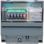
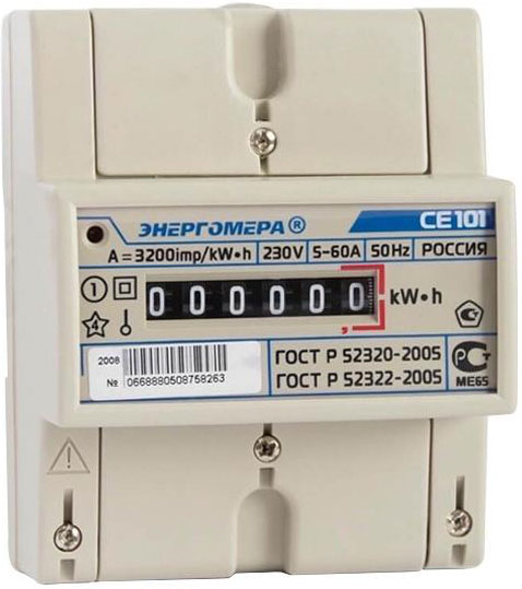
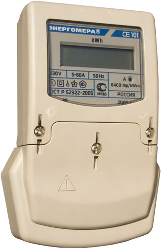
The CE-101 Energomer electric meter is common in single-phase AC networks for single-tariff metering of consumed electricity.
The counter belongs to modern devices, the use and use of which is recommended by energy supply organizations. Has a certificate of the State Register of Measuring Instruments
Content
Description of the device
The single-phase electricity meter is designed to be connected to an alternating current network with a voltage not exceeding 240 V to measure the active load. The rated load current is 5A, and the maximum is 60A for the 145 version or 10 and 100A for the 148 model.
The meter is available in 3 mounting options, which are indicated by additional markings in the designation of devices:
- S6 or S10 - fastening on the shield with 3 screws;
- R5 - fixing on a DIN rail;
- R5.1 - universal mount.
The current is measured by means of a shunt, which eliminates the possibility of electromagnetic interference.In addition, the measuring system and the reference mechanism have an electromagnetic shield and a backstop, making it impossible to steal electrical energy or distort readings.
Energomera CE 101 meter body is made of impact-resistant and non-combustible plastic.
A special feature is the low value of the starting current - 10mA, which provides high sensitivity (the power consumption starts from 2W).
The service life of the electric meter is at least 30 years.
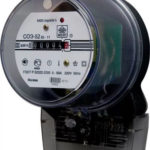
Light indicators
There are 1 or 2 LEDs on the front panel of electric meters. One of the LEDs labeled as "3200 imp/kW•h" or "1600 imp/kW•h" has 2 functions:
- continuous glow - connection to the network and the absence of power consumption;
- flickering is proportional to the load.
This indicator is available in all models of electric meters.
Models CE101 S6 and S10 are characterized by the presence of a second indicator "Robr", which lights up when there is reverse power.
The network and load indicator lights up with reduced brightness when the power consumption is below the threshold. When the load increases, the LED starts to turn on brightly for a period of 30-90 ms with a frequency proportional to the load.
By counting the number of counter pulses for a selected period of time, you can determine the amount of power consumed. This function of the CE 101 is useful for remote control and indicator failure.
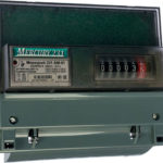
Features of the display board
The display board has several options. Each of the modifications of the indicator is reflected in the marking of the device:
- M6 - six-segment;
- M7 - seven-segment;
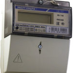
- the absence of the symbol "M" - liquid crystal.
Devices with an electronic liquid crystal display are more reliable because they have no moving parts, but are characterized by a narrower range of allowable operating temperatures. This is due to the fact that LCDs lose their functionality at large negative temperatures.
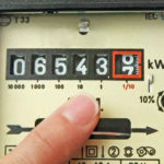
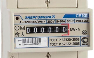
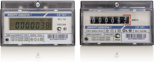 Mechanical indicator devices of CE 101 devices have an additional segment showing tenths of kilowatts. This section is circled on the indicator with a red border and is not taken into account when taking readings.
Connecting the device
Before connecting the meter, you need to familiarize yourself with its documentation and check the device numbers on the case and in the device form. A counter purchased in a store must have a form and an instruction manual. The manual contains the technical parameters of this device and its connection diagram.
Devices produced at different times may have some differences in connection, so you must use the diagram that is shown on the inside of the terminal block cover.
The switching circuit is universal and involves the connection of 4 conductors:
- 1- phase input (network);
- 3 - phase output (load);
- 4 - zero input (network);
- 5(6) - zero output (load).
Work on connecting the meter CE 101 can only be carried out in the absence of mains voltage. The order of work is as follows:
- turn off the power on the input cable;
- install a counter, introductory and load circuit breakers on the switchboard;
- strip the ends of the input cable;
- apply voltage and determine the phase wire with an indicator screwdriver and mark it;
- turn off the power again;
- clamp the input wires in the block terminals in accordance with the diagram;
- connect the load wires;
- supply food;
- check the presence of voltage at the output of the meter;
- connect the load and check that the meter reading increases in proportion to the load.
Each terminal has 2 screws. The length of the stripped insulation must be such that the bare conductor does not extend beyond the terminal and the insulation does not fall under the screws.
First, tighten the top screw, and then, making sure that the wire is clamped firmly, tighten the bottom one.
When using a stranded wire, it is necessary to crimp the ends with a special tip or irradiate and solder the wires.
Energy meter CE 101 will not work in case of intentional or accidental incorrect connection.
Modern electrical wiring is characterized by the presence of 3 conductors, one of which serves to connect the ground. This wire is not used in the electric meter switching circuit. The ground wire can be identified by the yellow-green color of the insulation.
Taking readings and checking meters
To take readings, only numbers that are not surrounded by a red border are taken into account, and for devices with liquid crystal indicators, only numbers up to a decimal point.
Verification of meters is carried out in specialized organizations. The calibration interval is 16 years. Extraordinary verification is carried out after repair. Devices on sale already have verification, but its period should not be more than 2 years. Otherwise, re-verification is required.
To protect against opening, CE electricity meters have a special holographic sticker. The screw fastening the body parts is sealed.The date of verification of the device is indicated on the seal.
Similar articles: